Gas bubble lifting instrument and use method thereof

A bubble riser, vertical technology, applied in the direction of instruments, measuring devices, measuring fluid pressure, etc., can solve the problems of low standardization of experimental models, influence of interfacial tension method, short time consumption, etc., to ensure consistency and reliability The effects of repeatability, ensuring consistency, and eliminating human errors

Active Publication Date: 2016-11-16
PETROCHINA CO LTD
View PDF3 Cites 3 Cited by
  • Summary
  • Abstract
  • Description
  • Claims
  • Application Information

AI Technical Summary

Problems solved by technology

At present, the test methods for obtaining the minimum miscible pressure (MMP) value of oil and gas include: thin tube test method, interfacial tension test method and bubble riser method. Among them, the thin tube test method is widely used in major oil companies and scientific research institutes, but The thin tube test method has the disadvantages of long time consumption (about 5 weeks), high cost, and low standardization of the experimental model, while the interfacial tension method is rarely used because it is seriously affected by human factors and its use is limited. , the riser method has the advantages of short time consumption and conforms to the CO 2 It has the advantages of flooding process and multiple contacts of oil and gas. Usually, the test of a sample can be completed within a few hours. Therefore, the bubble meter method has a very broad application prospect.

Method used


Image

  • Gas bubble lifting instrument and use method thereof
  • Gas bubble lifting instrument and use method thereof

Examples


Embodiment approach 1

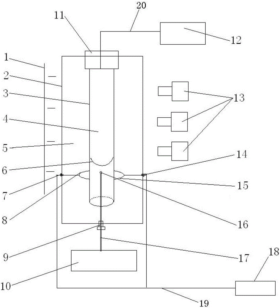
[0034] Such as figure 1 As shown, the present invention provides a foam riser, wherein the foam riser includes: a metal kettle 2, one side of which is provided with a plurality of cameras 13 along the vertical direction, and the other side is provided with a plurality of said The light source body 1 relative to the camera 13; the glass cylinder 3, which is located in the metal kettle 2, the upper end of the glass cylinder 3 is fixed on the top wall of the metal kettle 2 and is connected to the first pump 12, and the glass cylinder 3 The lower end of the cylinder 3 is an opening, and the glass cylinder 3 communicates with the metal kettle 2 through the opening; the gas injection needle tube 17, whose needle tail end is connected with the second pump 10, and the needle end passes through the metal kettle The bottom wall of 2 extends into the glass cylinder 3; two electromagnetic coils are connected to the controller 18, and the two electromagnetic coils are located in the metal ...

Embodiment approach 2

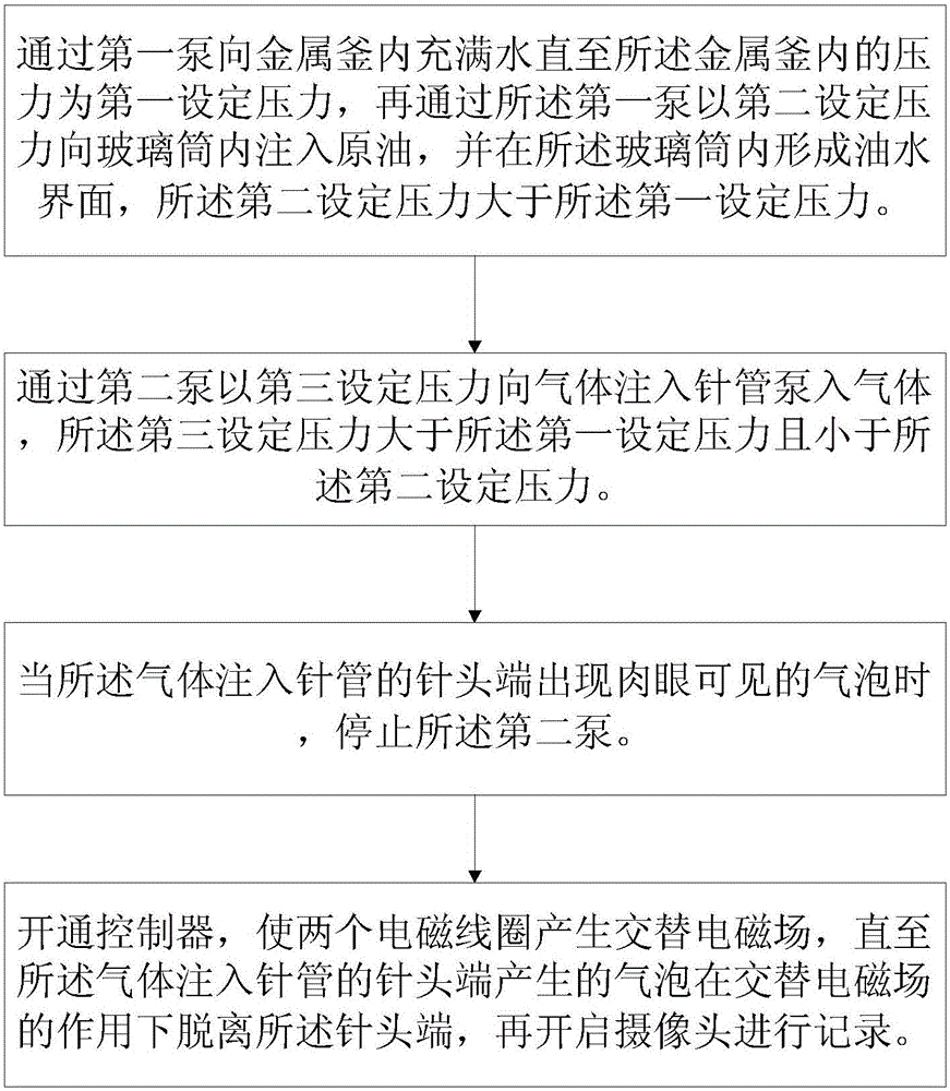
[0041] The present invention provides a method for using the foam riser described in Embodiment 1. The structure, working principle and beneficial effects of the foam riser in this embodiment are the same as those in Embodiment 1, and will not be repeated here. Such as figure 2 Shown, the using method of described bubble riser comprises the steps:

[0042] Step a: fill the metal kettle 2 with water 5 through the first pump 12 until the pressure in the metal kettle 2 reaches the first set pressure, and then fill the glass cylinder 3 with the second set pressure through the first pump 12 Inject crude oil 4, and form an oil-water interface 6 in the glass cylinder 3, and the second set pressure is greater than the first set pressure;

[0043] Step b: using the second pump 10 to pump gas into the gas injection needle 17 at a third set pressure, the third set pressure being greater than the first set pressure and lower than the second set pressure;

[0044] Step c: Turn on the co...


PUM


Abstract

The invention provides a gas bubble lifting instrument which comprises the components of a metal kettle, wherein one side of the metal kettle is provided with an image camera, and the other side is provided with a light source; a glass cylinder which is arranged in the metal kettle, wherein the glass cylinder is fixedly arranged in the metal kettle and is connected with a first pump, the lower end of the glass cylinder is provided with an opening, and the glass cylinder is communicated with the metal kettle; a gas injection needle tube of which the tail end is connected with a second pump, and the head end of the gas injection needle tube extends into the glass cylinder; and two electromagnetic coils which are connected with a controller, wherein the two electromagnetic coils are arranged in the metal kettle and are arranged at two sides of the glass cylinder. The invention further provides a use method of the gas bubble lifting instrument. The use method comprises the steps of a, filling the metal kettle with water by the first pump until an inner pressure reaches a first preset pressure, and injecting crude oil into the glass cylinder by the first pump through a second preset pressure which is higher than the first preset pressure; b, pumping gas into the gas injection needle tube by the second pump through a third preset pressure; and c, starting the controller for generating an alternative electromagnetic field until the gas bubble is separated from the needle head end, and then starting the image camera. The gas bubble lifting instrument realizes in-time separation and same size of the gas bubbles.

Description

technical field [0001] The invention relates to the field of oil and gas field development, and refers to a device for testing the minimum miscible pressure of oil and gas and a method for using the same, in particular to a bubble riser capable of assisting the detachment of bubbles and a method for using the same. Background technique [0002] In recent years, with the CO 2 With the continuous development of miscible flooding technology, the improvement of the measurement technology of oil and gas minimum miscible pressure (MMP) has also attracted much attention. 2 Accurate and fast acquisition of this value is the key for petroleum scientists to solve many technical problems of oil displacement. At present, the test methods for obtaining the minimum miscible pressure (MMP) value of oil and gas include: thin tube test method, interfacial tension test method and bubble riser method. Among them, the thin tube test method is widely used in major oil companies and scientific r...

Claims


Application Information

Patent Timeline
Patent Type & Authority Applications(China)
IPC IPC(8): G01L11/00
CPCG01L11/00
Inventor 张可李实陈兴隆杨胜建
Owner PETROCHINA CO LTD
Why Eureka
Try Eureka