Detachable bolt anchoring characteristic test bench

A characteristic test and dismantling technology, applied in the direction of strength characteristics, using stable tension/pressure test material strength, measuring device, etc., can solve the problems of excessive material waste, complicated experimental procedures, and prolonged experimental preparation time, and reduce The effect of test cost, improving test efficiency and shortening test preparation time

Active Publication Date: 2016-11-16
ANHUI UNIV OF SCI & TECH
View PDF10 Cites 6 Cited by
  • Summary
  • Abstract
  • Description
  • Claims
  • Application Information

AI Technical Summary

Problems solved by technology

Both of the above two technical solutions use ordinary steel pipes to simulate the surrounding rock as the anchoring device. In each test, a certain length of steel pipe must be cut to anchor the anchor rod in the steel pipe. After the experiment, the anchor rod cannot be taken out, and the steel pipe cannot be reused. On the one hand, steel is wasted, on the other hand, the experimental procedure is complicated and the experimental preparation time is prolonged
The Chinese invention patent with the patent application number 201310194762.5 discloses an experimental platform for bolt anchorage characteristics, which uses concrete to simulate the anchorage surrounding rock. This experimental method first prepares a concrete block, and then anchors the anchor bolt in the concrete block. On the one hand, the concrete block is easy to crack during the experiment and the test fails. On the other hand, after the experiment is over, the concrete cannot be reused after the experiment, that is, the concrete block must be prepared for each test. This experimental method has the disadvantages of material waste and preparation Disadvantages such as long time and large manpower consumption

Method used


Image

  • Detachable bolt anchoring characteristic test bench
  • Detachable bolt anchoring characteristic test bench
  • Detachable bolt anchoring characteristic test bench

Examples


Embodiment Construction

[0025] In order to make the technical means, creative features, objectives and effects achieved by the present invention easy to understand, the present invention will be further described below in conjunction with specific embodiments and illustrations.

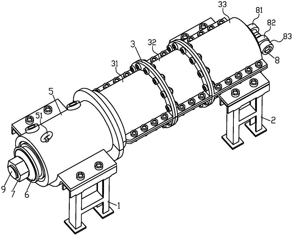
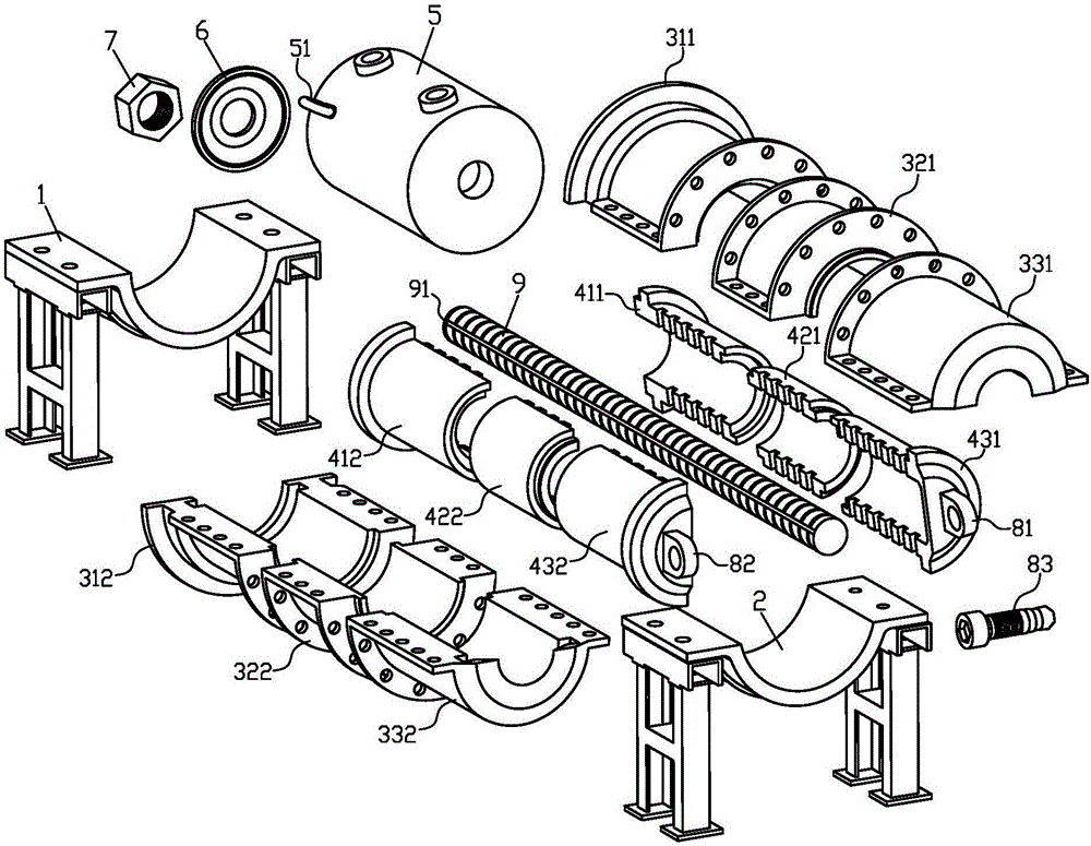
[0026] Such as figure 1 , figure 2 , Figure 5 and Figure 6 As shown, a detachable rock bolt anchoring characteristic test bench includes a front bracket 1, a rear bracket 2, a detachable fixer 3, a simulated anchor 4, an anchor puller 5, a tray 6, a nut 7, and an anchor Separator 8 and anchor rod 9. Wherein, the anchor rod pullout meter 5 is installed on the front bracket 1, and is used to apply an axial pulling force to the anchor rod 9 in the test, so as to measure the anchoring force, pull-out force and the bearing force of the anchor rod 9. The relationship between the pulling force and the displacement; the rear end of the detachable fixer 3 is installed on the rear bracket 2 for fixing and installing the simulat...


PUM


Abstract

The invention discloses a detachable bolt anchoring characteristic test bench which comprises a front support, a rear support, a detachable fixer, a simulated anchoring body, an anchor bolt drawing dynamometer, a tray, a nut, an anchoring body separator and an anchor bolt. The anchor bolt drawing dynamometer is mounted on the front support, the rear end of the detachable fixer is mounted on the rear support, the detachable fixer is connected with the anchor bolt drawing dynamometer through the anchor bolt, the tray and the nut, the simulated anchoring body is placed inside the detachable fixer, and the anchoring body separator is positioned at the tail of the simulated anchoring body and used for separating the simulated anchoring body into an upper portion and a lower portion. The detachable bolt anchoring characteristic test bench can be used for performing simulation and experimental research on bolt anchoring mechanism under complicated conditions, interaction relationship with surrounding rocks, stress distribution rules, bolt anchoring body bearing characteristics and the like, and has the advantages that anchoring lengths can be adjusted, an anchoring device can be detached and reused and the like. Experimental preparation time is greatly shortened, experimental cost is reduced, experimental efficiency is improved, and the shortcomings of the prior art can be overcome.

Description

technical field [0001] The invention belongs to the technical field of mine support, and in particular relates to a detachable test bed for anchorage characteristics of bolts. Background technique [0002] At present, bolt support has become a safe and efficient main support method for coal mine roadways, and has been widely promoted and applied in coal mine roadways in my country. Bolt support is to anchor the bolt in the coal rock body, tighten the nut at the end of the rod, apply prestress to the surrounding rock, and restrain the deformation, separation, expansion and slippage of the surrounding rock of the roadway. Studying the axial load and axial deformation performance of the bolt support process is of great significance to deepen the research on the bolt support mechanism, improve the reliability of the bolt support, and ensure the safety of the project. [0003] The bolt support method has become the main support and reinforcement method for shaft and geotechnical...

Claims


Application Information

Patent Timeline
IPC IPC(8): G01N3/08G01D21/02
CPCG01D21/02G01N3/08G01N2203/0017
Inventor 李英明孟祥瑞王成军高孝鹏
Owner ANHUI UNIV OF SCI & TECH
Why Eureka
Try Eureka