Apparatus for preparing and testing soil-rock interface sample for on-site direct shear test

A technology of sample preparation and test equipment, which is applied in the preparation of test samples, measurement equipment, and the use of stable shear force to test the strength of materials, etc., can solve the problems of increased risk, difficult labor, and heavy workload. Achieve the effects of reducing eccentricity, convenient installation and disassembly, and reducing friction

Active Publication Date: 2016-11-16
CHINA THREE GORGES UNIV
View PDF9 Cites 17 Cited by
  • Summary
  • Abstract
  • Description
  • Claims
  • Application Information

AI Technical Summary

Problems solved by technology

When conducting the test, generally excavate and prepare a large sample blank (length, width, and height are all greater than 500mm) at the selected test site, and then manually prepare the sample with a tool such as a soil cutter, but the manual preparation of the test sample The geometric size, angle, and flatness of the sample are often not standard, and it is difficult to meet the requirements of the tes...

Method used


Image

  • Apparatus for preparing and testing soil-rock interface sample for on-site direct shear test
  • Apparatus for preparing and testing soil-rock interface sample for on-site direct shear test
  • Apparatus for preparing and testing soil-rock interface sample for on-site direct shear test

Examples


Embodiment 1

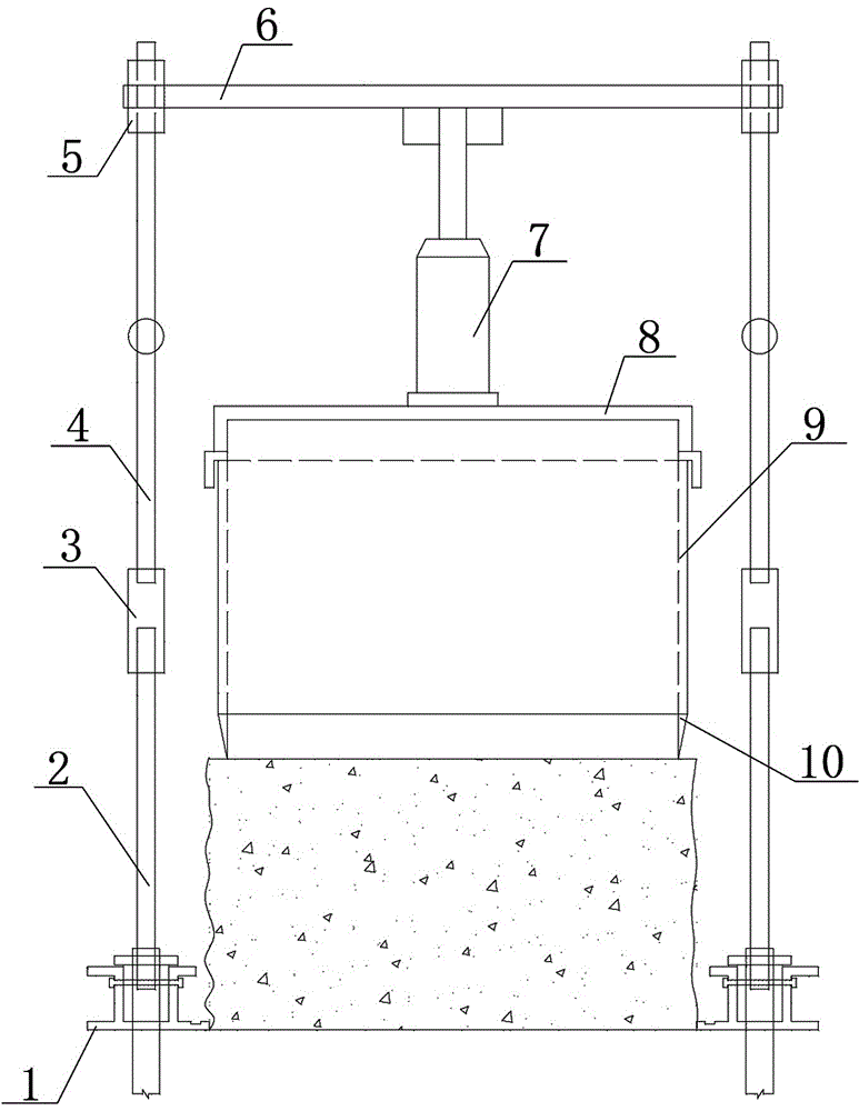
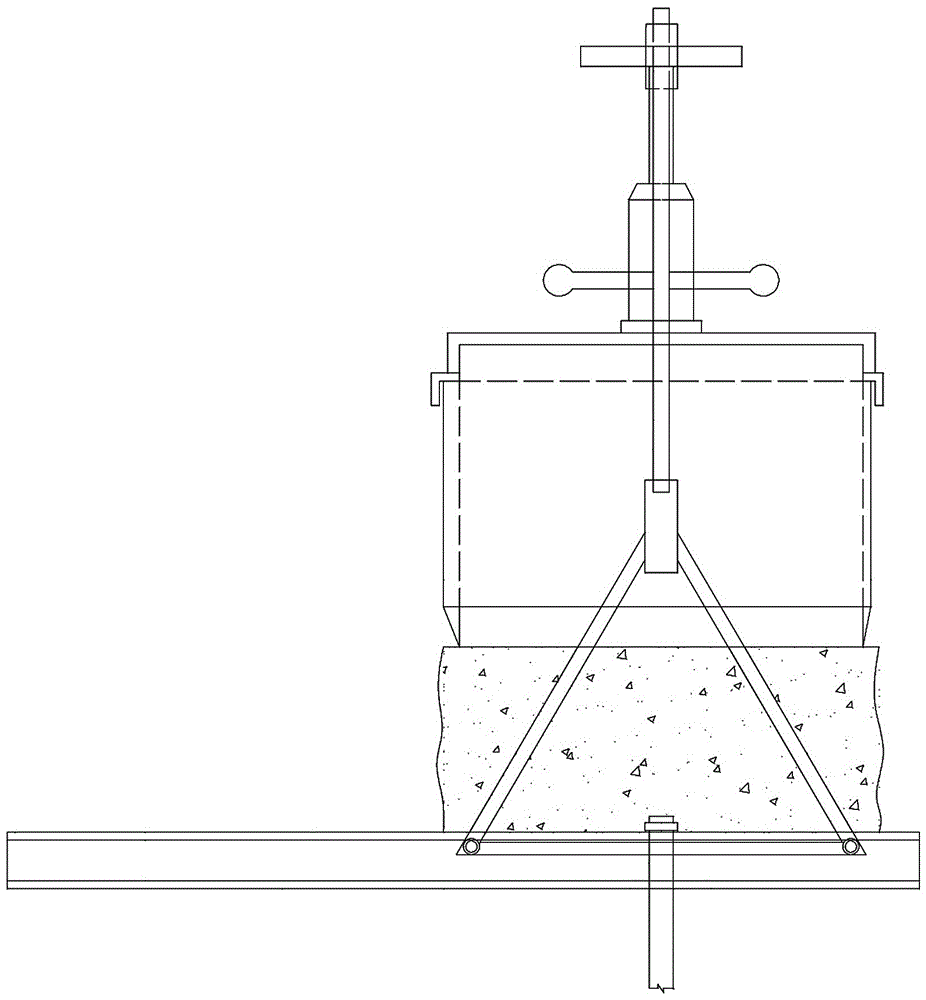
[0036] Embodiment 1: soil-rock interface field direct shear test sample preparation and test device, it comprises two mutually parallel rail frames 1, and rail frame 1 is provided with tripod 2, and tripod 2 top is provided with sleeve 3, and sleeve 3 The upper end is connected with a telescopic rod 4, and the telescopic rod 4 is connected with the top plate 6 through a sleeve 5, and a hydraulic jack 7 is vertically arranged below the top plate 6, and the hydraulic jack 7 is connected with the force transmission frame 8, and the lower end of the force transmission frame 8 is connected with the shear box 9 Connected, the shear box 9 is a square frame surrounded by sides around.

[0037] A detachable soil cutter 10 is installed at the lower end of the shearing box 9 .

[0038] A handle 19 is provided on the telescopic rod 4 .

[0039] When preparing soil samples, the following steps are included:

[0040] 1) Manually excavate a ring-shaped soil pit at the selected test site. T...

Embodiment 2

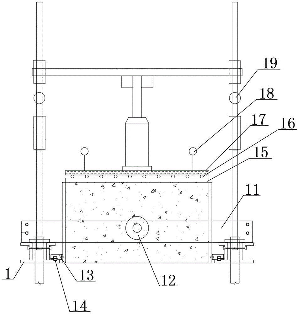
[0044] Embodiment 2: A horizontal loading frame 11 is erected on two mutually parallel guide rail frames 1 , and a horizontal jack 12 is provided perpendicular to the horizontal loading frame 11 and on a horizontal plane.

[0045] Both sides of shearing box 9 are provided with rolling guide box 13, and the wheels 14 on the rolling guide box are arranged in the roller track on the guide rail frame 1.

[0046] The shearing box 9 is provided with a lower pressure plate 15, an upper pressure plate 17 is arranged above the lower pressure plate 15, and a roller row 16 is arranged between the lower pressure plate 15 and the lower pressure plate 17.

[0047] On the force plate 17, a vertical displacement measuring device magnetic base and a dial gauge 18 are placed.

[0048] A method for loading a direct shear test comprising the following steps:

[0049] 1) After the sample preparation is completed, remove the soil cutter on the shear box, depressurize the jack and return it, first ...


PUM


Abstract

Disclosed is an apparatus for preparing and testing a soil-rock interface sample for an on-site direct shear test. The apparatus comprises two guiding rail supports arranged in parallel, tripods are arranged on the guiding rail supports, sleeves are arranged at the top parts of the tripods, and telescopic rods are connected to upper ends of the sleeves and connected to a top plate through sleeves. A hydraulic jack is vertically arranged below the top plate and connected to a load-transfer support, and the lower end of the load-transfer support is connected to a shear box which is a tetragonal frame made from four peripheral side faces. The invention provides a self-stabilized soil-rock interface on-site direct shear apparatus integrating sample preparation, loading and shearing into one body and a use method of the apparatus.

Description

technical field [0001] The present invention relates to a kind of on-the-spot soil mass direct shear test sample preparation and loading device, specifically, relate to the preparation device and the direct shear test loading device of the direct shear test sample of sliding zone on the soil-rock interface in the field of rock mechanics test, It is suitable for the shear strength test of bedrock and soil contact interface. Background technique [0002] With the development of science and technology, it is no longer enough to consider the safety and stability of the superstructure in the professional field of civil engineering, and the foundation, underground engineering, and slope engineering are gradually being studied in depth. These scientific studies are inseparable from soil and rock. At the same time, the failure and deformation of soil and rock are basically caused by shear failure, and the instability and failure of geotechnical engineering develop with the developme...

Claims


Application Information

Patent Timeline
IPC IPC(8): G01N3/24G01N1/28
CPCG01N1/286G01N3/24G01N2203/0025
Inventor 邓华锋王晨玺杰张恒宾方景成肖瑶李建林王哲张小景胡玉
Owner CHINA THREE GORGES UNIV
Why Eureka
Try Eureka