

Full-automatic loading-unloading and visual inspection device
A visual inspection, fully automatic technology, applied in measuring devices, analyzing materials, material analysis by optical means, etc., can solve the problem of low accuracy of subjective judgment of qualified and unqualified products, low production efficiency, easy to produce misjudgment, etc. problems, to avoid additional land occupation, save space, and facilitate assembly and transportation
- Summary
- Abstract
- Description
- Claims
- Application Information
AI Technical Summary
Problems solved by technology
Method used
Image


Examples
Embodiment Construction
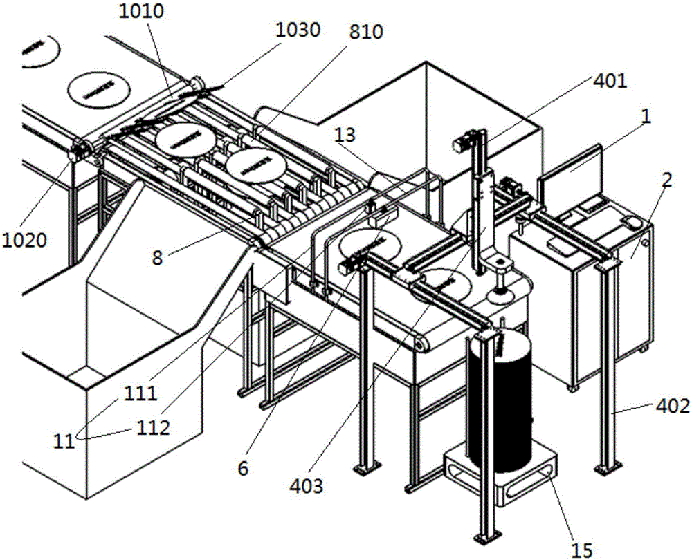
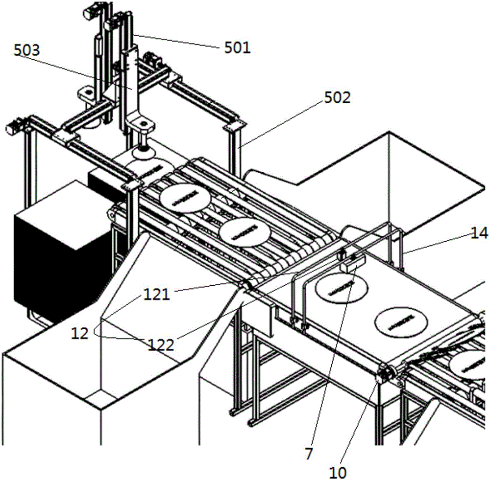
[0030]The technical solutions of the present invention will be further described in detail below in conjunction with the accompanying drawings and by way of listing some optional embodiments of the present invention. It should be noted that: any technical feature and any technical solution in this embodiment are one or more of a variety of optional technical features or optional technical solutions. Citing all the alternative technical features and alternative technical solutions of the present invention, it is not convenient for the implementation of each technical feature to emphasize that it is one of the optional multiple implementation modes, so those skilled in the art should know that: Replace any technical means provided by the present invention or combine any two or more technical means or technical features provided by the present invention with each other to obtain a new technical solution. Any technical features and any technical solutions in this embodiment do not...
PUM
 Abstract
Description
Claims
Application Information