RF PCB testing device based on RF probe and rotary joint base

A technology of rotating joints and testing devices, applied in RF circuit testing, electronic circuit testing and other directions, can solve the problems of long assembly time, waste of manpower and material resources, etc., to overcome the long time, reduce the waste of manpower and material resources, and improve the test efficiency. Effect

Inactive Publication Date: 2016-11-16
THE 724TH RES INST OF CHINA SHIPBUILDING IND
View PDF9 Cites 0 Cited by
  • Summary
  • Abstract
  • Description
  • Claims
  • Application Information

AI Technical Summary

Problems solved by technology

However, this method requires a long assembly time. If there is a problem with the performance of some printed boards, the printed board needs to

Method used


Image

  • RF PCB testing device based on RF probe and rotary joint base

Examples


Example Embodiment

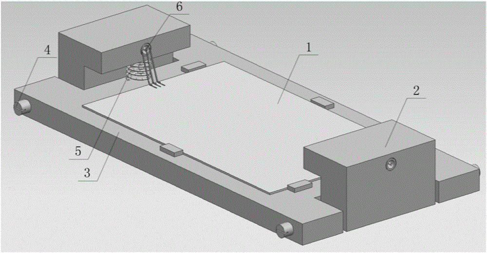
[0009] The schematic diagram of the test device of the present invention is as figure 1 Shown. The base 2 where the radio frequency probe is mounted is assembled on both ends of the base 3 where the printed board is mounted through the rotary joint 4 and the elastic device 5, so that the base 2 can be rotated and lifted and can be automatically compressed. The printed board base 3 can be designed with 4 uprights to provide positioning for the installation of the printed board, avoiding manual adjustment of the position of the printed board; the radio frequency probe 6 is installed on the base 2 with flexibility, so that the probe and the printed board The RF port of the board can be well contacted. During the test, only the base 2 with elastic radio frequency probes is installed at both ends, and the radio frequency printed board 1 to be tested is placed in the middle of the base 3 where the printed board is installed to perform the test.

[0010] The specific test steps of the...


PUM


Abstract

The invention relates to an RF PCB testing device based on RF probes and a rotary joint base for aiming at an RF PCB. Through a rotary joint and a spring, a base on which RF probes are mounted is assembled with the base on which a PCB is mounted, so that the base on which the RF probe is mounted has functions of rotatable lifting and automatic compaction, wherein the RF probes are elastic probes so that the probes can well contact with RF ports of the PCB. On a PCB base, four columns are utilized for performing a positioning function in mounting of the PCB. In testing, testing can be performed just through lifting the base which are provided with the RF probes at two ends and placing a to-be-tested PCB at the central part of the base on which the PCB is mounted. According to the RF PCB testing device, screening testing can be performed before the RF PCB is mounted into a module, thereby overcoming defects of long time in mounting the PCB into the module and troublesome detachment. Furthermore efficiency in testing the RF PCB can be effectively improved.

Description

technical field [0001] The invention relates to a radio frequency printed board testing device, in particular to a radio frequency printed circuit board based on a radio frequency probe and a rotary joint base, which can quickly test and batch test the radio frequency performance of the radio frequency printed board before it is loaded into a module. Board test setup. Background technique [0002] With the development of electronic technology, the mass production and inspection of printed boards has become an important research topic. At present, printed board manufacturers usually use X-ray detectors to detect whether the printed boards are processed correctly; surface mount manufacturers usually use X-ray detectors to detect the surface mount effect of components on printed boards, whether there is a short circuit or a virtual solder joint. However, since many surface-mount devices are packaged in QFN or BGA, X-ray inspection cannot completely rule out the possibility of ...

Claims


Application Information

Patent Timeline
IPC IPC(8): G01R31/28
CPCG01R31/2822
Inventor 周永春吴元清赖一成夏伟郭睿
Owner THE 724TH RES INST OF CHINA SHIPBUILDING IND
Why Eureka
Try Eureka