Reflection-type electro-optic phase modulator

An electro-optical phase modulation and reflective technology, applied in instruments, optics, nonlinear optics, etc., can solve problems such as unfavorable electro-optical phase modulators and increase in length of optical waveguides, and achieve easy integration, reduced structure size, and increased function. effect of length

Inactive Publication Date: 2016-11-16
GLOBAL ENERGY INTERCONNECTION RES INST CO LTD +1
View PDF4 Cites 5 Cited by
  • Summary
  • Abstract
  • Description
  • Claims
  • Application Information

AI Technical Summary

Problems solved by technology

[0010] In order to meet the technical requirements of electro-optic phase modulators used in the above fields, the half-wave voltage needs to be reduced as much as possible. At present, the half-wave voltage is usually reduced by increasing the length of the electro-optic phase modulator, but the increase in the length of the optical waveguide is not conducive to electro-optic phase modulation. The production, packaging and application of the device further limit the reduction of the half-wave voltage

Method used


Image

  • Reflection-type electro-optic phase modulator
  • Reflection-type electro-optic phase modulator
  • Reflection-type electro-optic phase modulator

Examples


Embodiment Construction

[0050] In order to make the purpose, technical solutions and advantages of the embodiments of the present invention more clear, the technical solutions in the embodiments of the present invention will be clearly and completely described below in conjunction with the accompanying drawings in the embodiments of the present invention. Obviously, the described embodiments It is a part of embodiments of the present invention, but not all embodiments. Based on the embodiments of the present invention, all other embodiments obtained by persons of ordinary skill in the art without making creative efforts belong to the protection scope of the present invention.

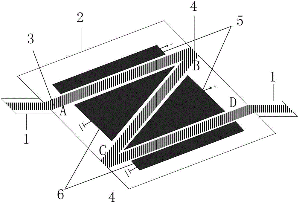
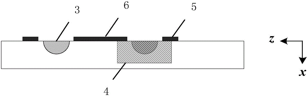
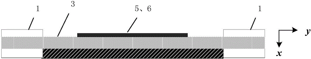
[0051] A reflective electro-optical phase modulator provided by an embodiment of the present invention will be described below with reference to the accompanying drawings.

[0052] The electro-optic phase modulator in this embodiment includes an electro-optic crystal, an optical waveguide and a modulation electrode. in,

[0...


PUM


Abstract

The invention provides a reflection-type electro-optic phase modulator. The reflection-type electro-optic phase modulator comprises an electro-optic crystal, optical waveguide and modulation electrodes; the optical waveguide comprises n first light paths and n+1 second light paths, wherein n is greater than or equal to 2; the first light paths are sequentially arranged between a light-in surface and a light-out surface of the electro-optic crystal; the second light paths are connected between the light-out end of the ith first light path and the light-in end of the i+1 first light path, wherein i is equal to 1, 2, ..., n; high-reflection films are arranged at the connecting positions of the first light paths and the second light paths; the modulation electrodes are arranged on the two sides of the first light paths and the second light paths respectively. Compared with the prior art, according to the reflection-type electro-optic phase modulator, multiple Z-shaped light paths are adopted to form the optical waveguide, the action length of the electro-optic phase can be increased under the condition of not increasing the length of the electro-optic phase modulator, and half-wave voltage is lowered. Meanwhile, the structural size of the electro-optic phase modulator can be reduced, integration is easy, and the practicability of the electro-optic phase modulator is improved.

Description

technical field [0001] The invention relates to the technical field of optical waveguide devices, in particular to a reflective electro-optical phase modulator. Background technique [0002] The electro-optic phase modulator is a photoconductive device that modulates the phase of light waves based on the linear electro-optic effect of crystals. For example, the direct waveguide electro-optical phase modulator made of lithium niobate crystal material controls the refractive index of the lithium niobate optical waveguide to change linearly with the applied electric field through the external modulation electric field, so that the phase of the lithium niobate optical waveguide changes with the The external modulation electric field changes to realize the phase modulation of the light wave. [0003] Electro-optic phase modulators play an important role in the fields of optical communication, optical sensing and microwave photonics technology, specifically: [0004] 1. Field of...

Claims


Application Information

Patent Timeline
Patent Type & Authority Applications(China)
IPC IPC(8): G02F1/035
CPCG02F1/035
Inventor 陈硕刘占元侯继彪牛晓晨郑天祥李璐孙海江李春城
Owner GLOBAL ENERGY INTERCONNECTION RES INST CO LTD
Why Eureka
Try Eureka