
Azimuth-pitch movement two-shaft seat rack

An azimuth and axle seat technology, which is applied to the machine/support, control using feedback, supporting the machine, etc., can solve the problems of high driving power, accumulation of driving joint errors, and cumbersome structure, and achieve the effect of convenient operation and simple structure.

Active Publication Date: 2016-11-16
XIDIAN UNIV
View PDF6 Cites 21 Cited by
  • Summary
  • Abstract
  • Description
  • Claims
  • Application Information

AI Technical Summary

Problems solved by technology

[0004] The purpose of the present invention is to provide an azimuth-tilt motion two-axis mount, aiming to solve the problems of the traditional serial azimuth-tilt mount for large-scale instruments and equipment with huge mass, very heavy structure, large drive power, and accumulation of drive joint errors The problem

Method used


Image

  • Azimuth-pitch movement two-shaft seat rack
  • Azimuth-pitch movement two-shaft seat rack
  • Azimuth-pitch movement two-shaft seat rack

Examples


Embodiment Construction

[0039] In order to make the object, technical solution and advantages of the present invention more clear, the present invention will be further described in detail below in conjunction with the examples. It should be understood that the specific embodiments described here are only used to explain the present invention, not to limit the present invention.

[0040] The application principle of the present invention will be described in detail below in conjunction with the accompanying drawings.

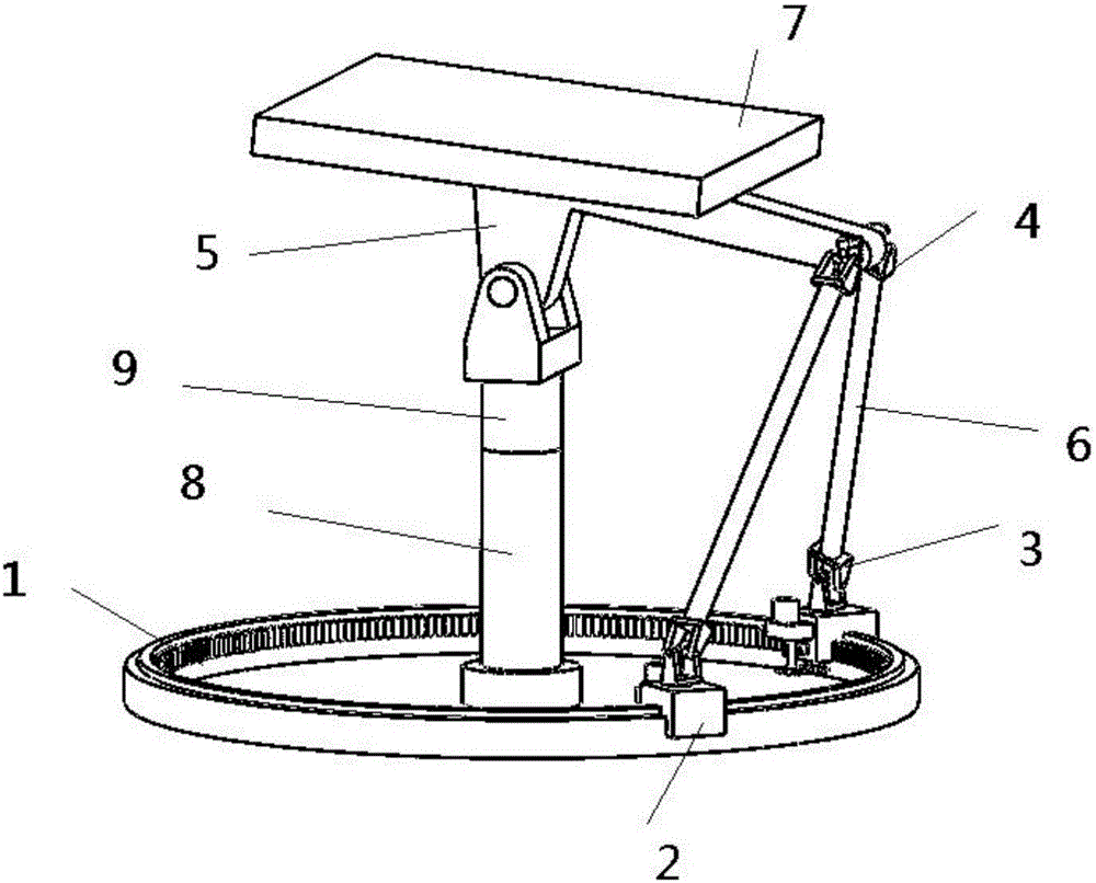
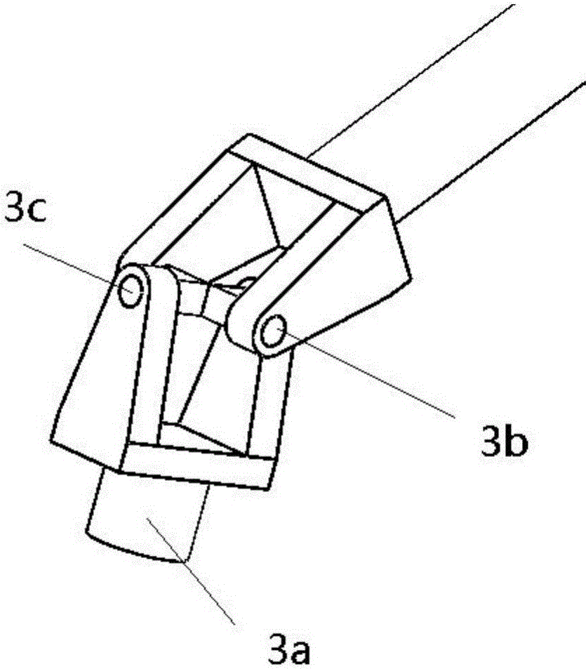
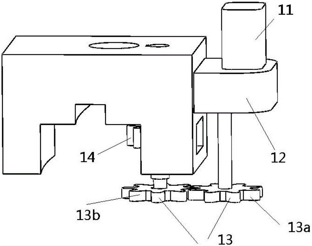
[0041] Such as figure 1 As shown, the azimuth-pitch two-axis mount of the embodiment of the present invention includes: a circular track 1, a sliding mechanism 2, a three-rotational degree of freedom compound hinge 3, a Hooke hinge 4, a first rotating pair 5, a connecting rod 6, and a rotating platform 7 , column 8, second revolving pair 9, servo motor 11, speed reducer 12, gear pair 13, rack 14.

[0042] The geometric center of the rotary platform carrying the instrument or equipmen...


PUM


Abstract

The invention discloses an azimuth-pitch movement two-shaft seat rack which is provided with a circular rail. The vertical axis of a vertical column is at the center of the circular rail, and the vertical column is connected to a rotation platform through the first rotation pair with a horizontal axis and is connected to a rack or ground through a second rotation pair with a vertical axis. The upper ends of two connection rods are connected to the rotation platform through hookjoints, and a sliding mechanism and the lower end of the connection rod are connected by using a composite hinge with three degrees of rotation freedom. According to the azimuth-pitch movement two-shaft seat rack, 0-degree to 90-degree pitch movement and -180-degree to 180-degree azimuth movement can be realized, external equipment can be a radar antenna, an astronomy radio camera, a camera, a sunlight reflector, and a solar energy sailboard. The structure is simple, the operation is convenient, and the problems of a heavy structure, a large driving power, and driving joint error accumulation of a traditional series connection type azimuth-pitch seat frame for large-scale apparatus equipment with a large quality are solved.

Description

technical field [0001] The invention belongs to the technical field of large-scale instrument mounts, in particular to an azimuth-pitch motion two-axis mount. Background technique [0002] At present, the azimuth-tilt mount is a simple two-axis rotation mechanism, which is used to support various instruments or equipment and perform rotation around two mutually perpendicular axes (one is a vertical axis and the other is a horizontal axis). The rotation around the vertical axis changes the orientation angle of the supporting device, which is usually called azimuth motion; the rotation around the horizontal axis changes the levelness of the supported object, which is usually called pitch motion. The traditional azimuth-tilt mount usually adopts the mature structural form as follows: two mutually perpendicular rotating shafts (revolute joints) that can be actively controlled form an azimuth-tilt mount. Each shaft joint is driven by a servo motor and a reduction gear train. Th...

Claims


Application Information

Patent Timeline
Patent Type & Authority Applications(China)
IPC IPC(8): G05D3/12
CPCG05D3/12F16M11/10F16M11/18F16M11/2014
Inventor 段学超保宏段宝岩冯树飞程璧
Owner XIDIAN UNIV
Learn More