Drive-control LED digital display screen

A drive control and display technology, applied to static indicators, instruments, identification devices, etc., can solve the problems of low installation efficiency of LED digital display, failure to realize drive control function, single display function, etc.

Pending Publication Date: 2016-11-16
ZHONGSHAN YOUYANG OPTOELECTRONICS TECH
View PDF5 Cites 4 Cited by
  • Summary
  • Abstract
  • Description
  • Claims
  • Application Information

AI Technical Summary

Problems solved by technology

[0003] The applicant found that the traditional LED digital screen only has LED wafers and wiring inside, and uses guide pins to connect with the outside. It only has a single display function and cannot realize the drive control function. When connecting with guide pins, the staff needs to correspond the guide pins of the LED digital display with the

Method used


Image

  • Drive-control LED digital display screen
  • Drive-control LED digital display screen
  • Drive-control LED digital display screen

Examples


Embodiment Construction

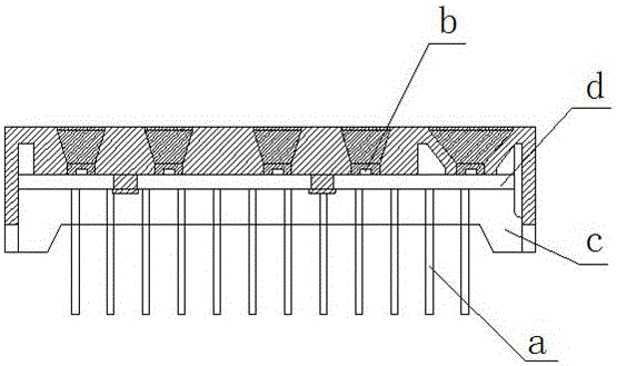
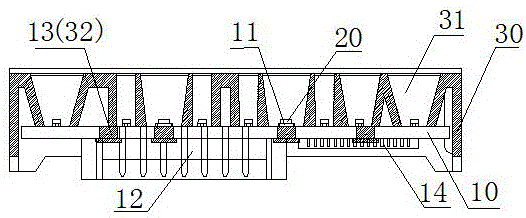
[0030] Such as figure 2 As shown, it shows a schematic diagram of a drive-controlled LED digital display provided by an embodiment of the present invention. The LED digital display includes: a PCB board 10, a preset number of LED patch lamps 20, and a plastic shell 30 ;

[0031] Wherein, the PCB board 10 includes a preset number of LED pads 11 arranged on the PCB board 10 according to a preset track, and the preset number of LED pads 11 are connected to the socket 12 through the circuit on the PCB board 10 and the general communication port. Corresponding to the connection, the PCB board 10 also includes an LED driver chip 14 integrated in the PCB board, and the PCB board 10 also includes a preset number of positioning holes 13 .

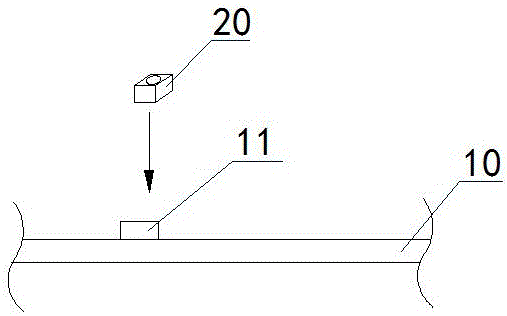
[0032] A preset number of LED patch lamps 20 are correspondingly mounted on a preset number of LED pads 11 on the PCB 10 by welding.

[0033] Such as image 3 As shown, it shows a schematic mounting diagram of an LED patch lamp provided by an ...


PUM


Abstract

The invention relates to a drive-control LED digital display screen, and belongs to the technical field of display. The LED digital display screen comprises a PCB, LED patch lamps and a plastic shell; the PCB comprises a preset number of LED bonding pads which are arranged on the PCB, the LED bonding pads are correspondingly connected with a universal communication port connection socket through circuits, and the PCB further comprises an LED driving chip and positioning holes; each LED patch lamp is installed on the corresponding LED bonding pad of the PCB in an attached mode; the surface side of the plastic shell is provided with reflection cavities, the position of the center of the bottom cavity opening of each reflection cavity corresponds to one LED patch lamp, the back side of the plastic shell is provided with positioning columns, and the positioning columns and the positioning holes in the PCB are riveted in an aligned mode respectively. According to the LED digital display screen, the LED driving chip is integrated into the LED digital display screen, modularization and integration of the LED digital display screen and the drive control function are achieved, connection with an electric appliance control panel adopts the universal communication port connection socket instead of a guide needle pin connection mode of a traditional LED digital display screen, and installation is more standardized and simplified.

Description

technical field [0001] The invention relates to the field of display technology, in particular to a drive-controlled LED digital display screen. Background technique [0002] The manufacturing process of the traditional LED digital display usually adopts the way of guide pins to connect the light source, PCB (Printed Circuit Board, printed circuit board) board and plastic shell and other components through the guide pin pins. The light source used is LED Epistar. When manufacturing the LED digital display, the staff binds the LED crystal to the PCB board through the binding process, and then conducts the positive and negative poles of the LED crystal by welding the metal welding wire, and finally the finished LED digital display is manufactured through The guide pins on the PCB board are connected to the electrical control board, such as figure 1 As shown, it shows a schematic diagram of a traditional LED digital display, where a is a guide pin, b is an LED chip, c is a ...

Claims


Application Information

Patent Timeline
IPC IPC(8): G09F9/33G09G3/32
CPCG09F9/33G09G3/32
Inventor 胡林奇叶顺升
Owner ZHONGSHAN YOUYANG OPTOELECTRONICS TECH
Why Eureka
Try Eureka