

Manufacturing method of solar cell and solar cell
A technology for a solar cell and a manufacturing method, which is applied in the field of solar cells, can solve problems such as the complexity of the solar cell manufacturing process, and achieve the effects of low resistance, high transmittance, and increased oxidation amount.
- Summary
- Abstract
- Description
- Claims
- Application Information
AI Technical Summary
Problems solved by technology
Method used
Image

Examples
Embodiment approach 1
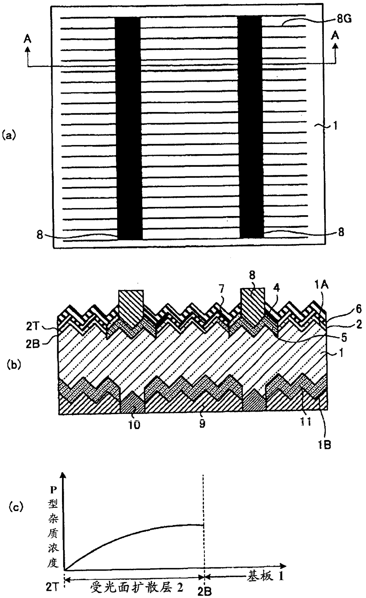
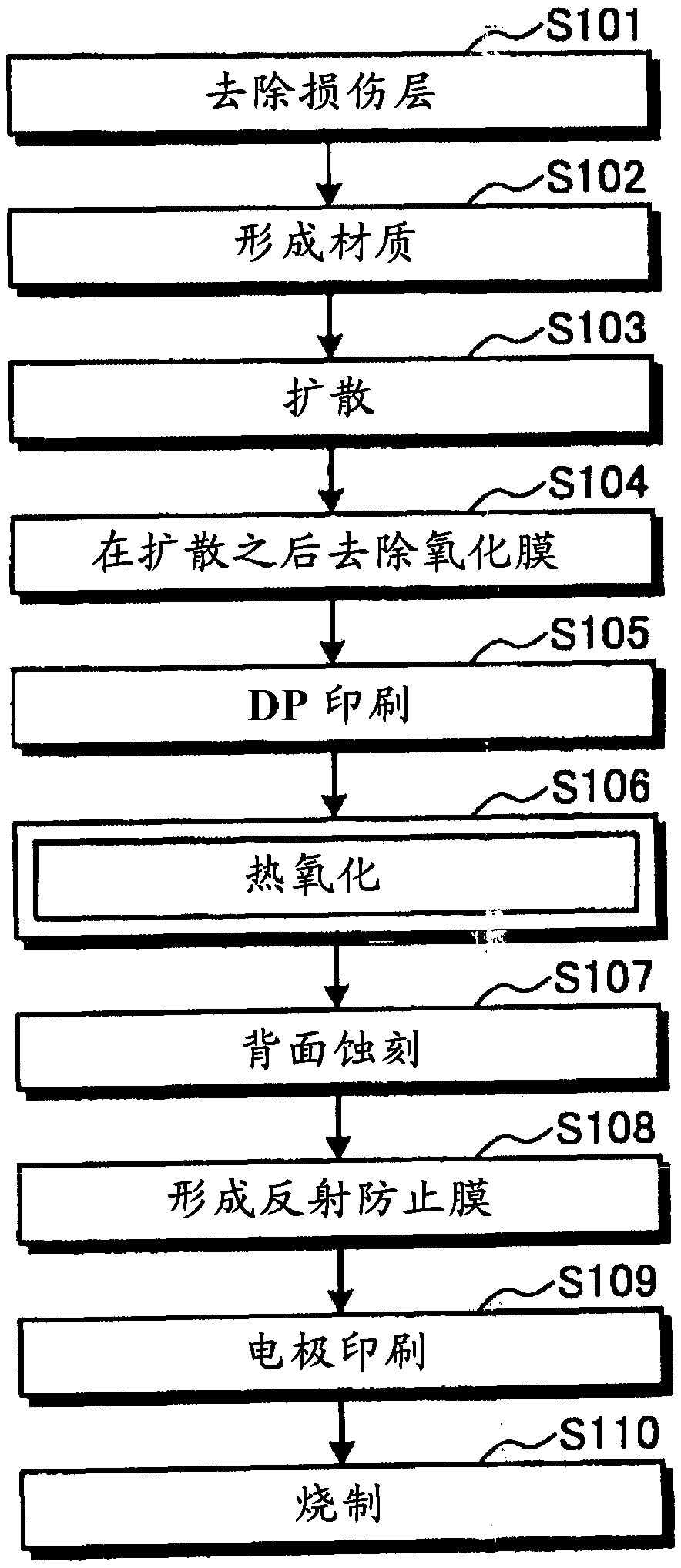
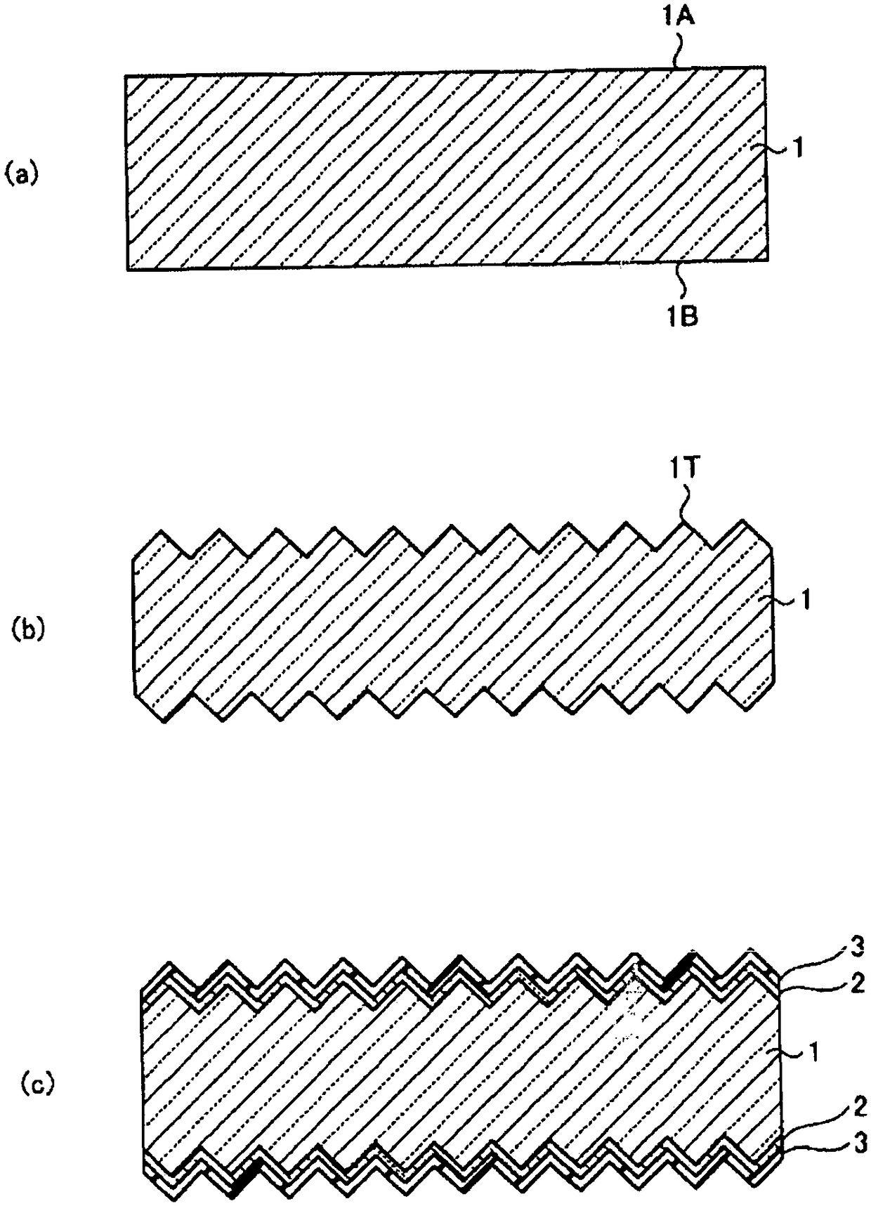
[0035] First, in the method of Embodiment 1, a case will be described in which an oxide film formed during diffusion over the entire surface of which a diffusion layer is formed is removed and a film during thermal oxidation formed during selective diffusion remains. figure 1 It is a figure which shows the solar cell of Embodiment 1, (a) is a top view, (b) is AA sectional drawing of (a), (c) is explanatory drawing which shows the concentration distribution of the diffusion layer of a light receiving surface. figure 2 It is a figure showing the flow chart explaining its manufacturing process, image 3 (a)~(c), Figure 4 (a)~(c) and Figure 5 (a) to (c) are process sectional views showing the manufacturing process of the solar cell according to the first embodiment.
[0036] In this embodiment, when the high-concentration diffusion layer 5 is formed on a part of the first surface 1A of the substrate 1 on which the diffusion layer 2 on the light-receiving surface is formed, th...
Embodiment approach 2
[0051] In Embodiment 1, doping paste 4 is formed after removing oxide film 3 formed in the diffusion step (step S103 ), but in this embodiment, oxide film 3 is left as it is. process. By remaining the oxide film 3 formed at the time of diffusion, a high passivation effect is obtained. Figure 6 is a diagram showing a solar cell according to Embodiment 2, Figure 7 It is a figure showing the flow chart explaining its manufacturing process, Figure 8 (a)~(c), Figure 9 (a) and (b) are process sectional views. Such as Figure 6 As shown, the solar cell of this embodiment and figure 1 The solar cell according to Embodiment 1 differs only in that the oxide film 3 remains on the light-receiving surface side, and is the same as the solar cell according to Embodiment 1 in other respects. Therefore, description is omitted here, and the same reference numerals are assigned to the same parts. Also in this embodiment, as in Embodiment 1, the thermal oxide film 6 formed by thermal o...
Embodiment approach 3
[0064] In Embodiment 1 described above, the thermally oxidized film 6 formed in the thermal oxidation step (step S106) was left as it is without being removed, and the backside etching (S107) and antireflection film forming step (S108) were performed, but in this In the embodiment, the oxide film 3 formed at the time of diffusion is removed, and the thermal oxide film 6 which is a film at the time of thermal oxidation is also removed to describe a case where it does not remain. Figure 10 is a diagram showing a solar cell according to Embodiment 3, Figure 11 It is a figure showing the flow chart explaining its manufacturing process, Figure 12 (a)~(c), Figure 13 (a) to (d) are process sectional views. The solar cell of this embodiment and figure 1 Compared with the solar cell of the first embodiment shown, the only difference is that the thermal oxide film 6 is not left on the light-receiving surface side, and the other points are the same as the solar cell of the first e...
PUM
 Abstract
Description
Claims
Application Information