A multi-point long-pin connector that is convenient to disassemble and assemble and disassemble method thereof

A technology that facilitates disassembly and assembly of connectors. It is applied in the direction of connection, coupling device, assembly/disassembly of contact pieces, etc. It can solve the problems of small operating space, burnt circuit, damage, etc., achieve low-cost equipment assembly, and avoid pin insertion Effect of damage, easy lifting and separation

Active Publication Date: 2014-07-09
BEIJING RES INST OF TELEMETRY
View PDF0 Cites 4 Cited by
  • Summary
  • Abstract
  • Description
  • Claims
  • Application Information

AI Technical Summary

Problems solved by technology

In the past, the assembly of this kind of equipment was generally carried out by visual inspection, and the mating of the connectors was realized by visual inspection and hand feeling. Because the operating space was too small, the visual inspection was not enough, and blind insertion was actually formed. See Figure 5 , there will inevitably be positioning errors, and it is difficult to achieve accurate alignment of the pins and sockets by visual inspection, which will cause damage to the pins, affect electrical performance, and even cause damage to the pins or even burn out the circuit; when disassembled, It is to insert the special tool between the corresponding bosses on the outside of the two housings where the circuit board is installed, see Image 6 , tilt the shell open, and then pull out the two connectors by hand
Sometimes the pins are deformed, damaged, or even scrapped due to eccentric force
At the same time, in the process of prying the shell, the special tool will damage the paint film on the outer surface of the product, affecting the appearance and anti-corrosion effect of the shell

Method used


Image

  • A multi-point long-pin connector that is convenient to disassemble and assemble and disassemble method thereof
  • A multi-point long-pin connector that is convenient to disassemble and assemble and disassemble method thereof
  • A multi-point long-pin connector that is convenient to disassemble and assemble and disassemble method thereof

Examples


Embodiment Construction

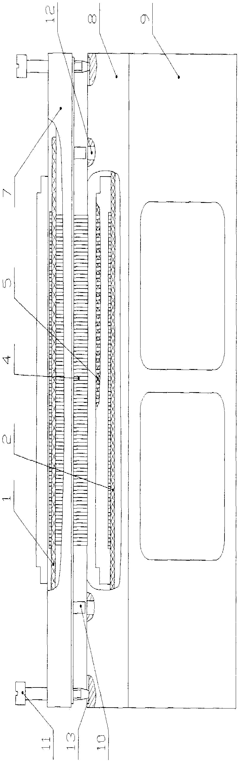
[0028] Below in conjunction with accompanying drawing and specific embodiment the present invention is described in further detail:

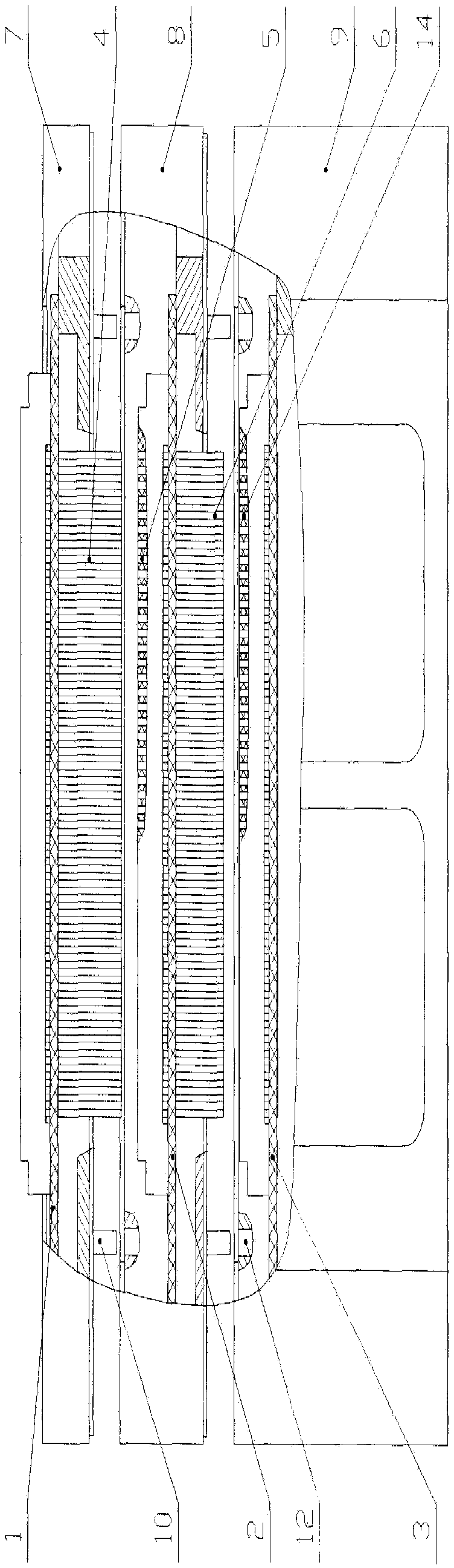
[0029] Such as figure 1 Shown is the structural representation of multi-point long-pin connector of the present invention, as figure 2 Shown is the schematic diagram of the structural decomposition of the multi-point long-pin connector of the present invention. In this example, three connector units are included. The connector unit includes a printed board, a connector and a housing, and the connector is composed of a jack and pins. Depend on figure 2 It can be seen that the pin 4 installed under the printed board 1 in the first layer of connector unit cooperates with the jack 5 installed above the printed board 2 in the second layer of connector unit, and the second layer of connector unit is installed on the printed board 1. The pins 6 below the printed board 2 cooperate with the jacks 14 installed above the printed board 3 in the third-l...


PUM


Abstract

The invention relates to a multi-point long-pin connector which is convenient for disassembly and assembly and a disassembly method thereof, comprising a plurality of connector units and lifting screws, wherein among any adjacent upper and lower connector units, the upper The pin part exposed under the printed board in the unit cooperates with the jack part welded above the printed board in the lower connector unit. Two guide pins are arranged on the shell of the upper connector unit, and the lower connector unit There are two guide holes matched with the guide pins on the housing. In addition, there are threaded holes on the four corners of the upper connector unit housing. When the upper and lower connector units are separated, the lifting screws are inserted into the threaded holes. In the middle, and make the end of the pulling screw withstand the concave surface of the lower connector unit housing, the present invention adds guiding structural elements in the structural design to ensure the precise positioning of the connector during assembly, greatly improving the manufacturability of assembly, and even Realize blind insertion, and realize reliable, stable, efficient and low-cost equipment assembly.

Description

technical field [0001] The invention belongs to the technical field of electronic equipment structure design, and relates to a multi-point long-pin connector which is convenient for disassembly and assembly and a disassembly method thereof. Background technique [0002] Due to the requirement of small size and multiple functions for electronic equipment in some fields at present. Therefore, some electronic devices are designed by stacking multiple circuit boards. In order to realize the electrical connection between adjacent circuit boards, in-line multi-point long-pin connectors are often used. In the past, the assembly of this kind of equipment was generally carried out by visual inspection, and the mating of the connectors was realized by visual inspection and hand feeling. Because the operating space was too small, the visual inspection was not enough, and blind insertion was actually formed. See Figure 5 , there will inevitably be positioning errors, and it is difficu...

Claims


Application Information

Patent Timeline
Patent Type & Authority Patents(China)
IPC IPC(8): H01R12/70H01R43/20
Inventor 齐雪梅李斌鲁玉芳张丽萍
Owner BEIJING RES INST OF TELEMETRY
Why Eureka
Try Eureka