Mechanism for detecting and driving distal thumb joint of human hand

A driving mechanism and hand-thumb technology, applied in the field of data gloves, can solve the problems of high price of force feedback data gloves, complex systems, and difficult maintenance.

Inactive Publication Date: 2016-11-23
钦州市科海奇科技有限公司
View PDF3 Cites 1 Cited by
  • Summary
  • Abstract
  • Description
  • Claims
  • Application Information

AI Technical Summary

Problems solved by technology

[0003] The purpose of the present invention is to solve the disadvantages of the existing force feedback data gloves, such as high price, complex system, and difficult maintenance, and proposes a combination of an external angle sensor and a joint two-way active drive devi...

Method used


Image

  • Mechanism for detecting and driving distal thumb joint of human hand
  • Mechanism for detecting and driving distal thumb joint of human hand
  • Mechanism for detecting and driving distal thumb joint of human hand

Examples


specific Embodiment approach 1

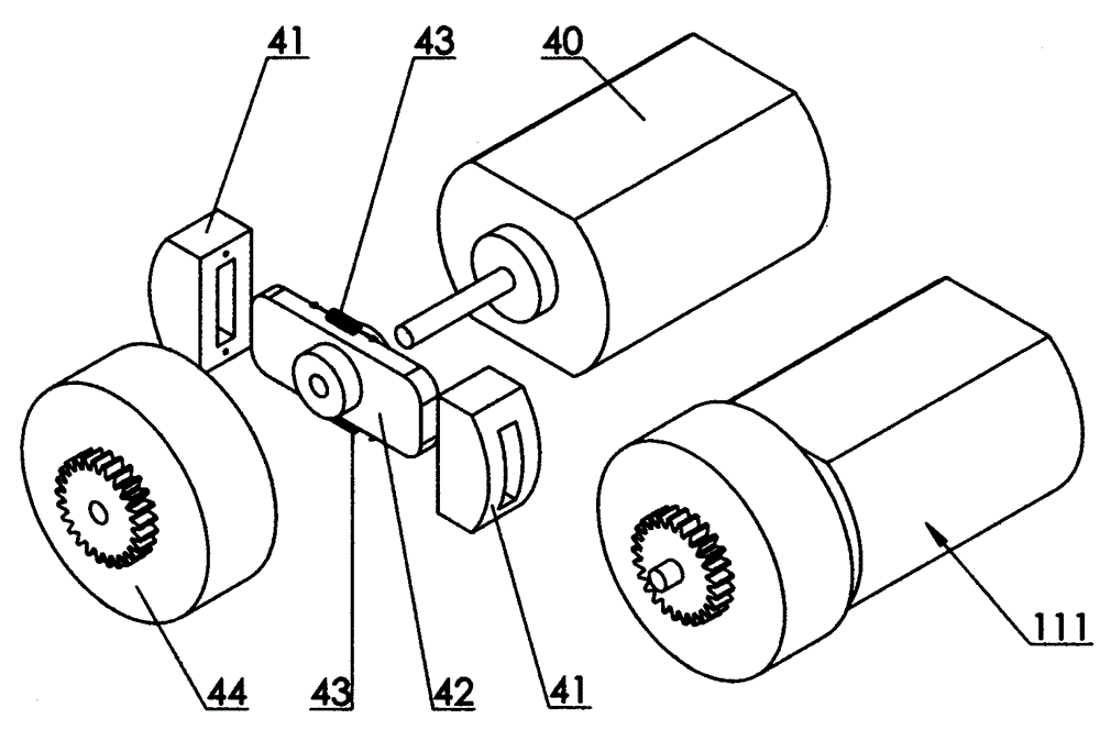
[0007] Specific implementation mode one: image 3 As shown, the human thumb distal joint detection driving mechanism includes a driving part 111, and the driving part 111 includes a motor 40 and a clutch device, and the clutch device is composed of a clutch device friction plate 41, a friction plate slide bar 42, and The extension spring 43 and the clutch device cover 44 are composed of the friction plate slide bar 42 and the shaft of the motor 40, and the two clutch device friction plates 41 are inserted into the two ends of the friction plate slide bar 42 respectively, and between the two clutch device friction plates 41 A return extension spring 43 is connected, and the clutch cover 44 is inserted into the shaft of the motor 40. The clutch cover 44 is in sliding contact with the shaft of the motor 40, and the clutch cover 44 is provided with transmission gears. Action implementation process: when the rotation speed of the motor 40 is higher than a certain value, the two fri...

specific Embodiment approach 2

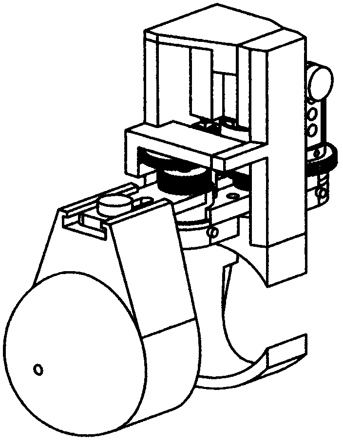
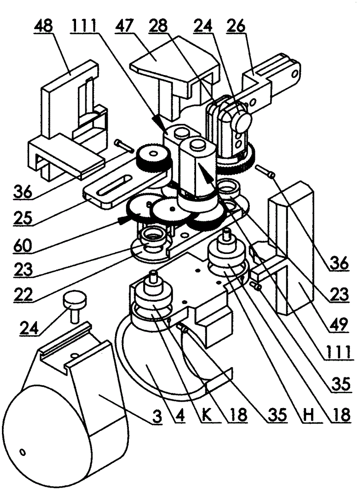
[0008] Specific implementation mode two: as figure 1 , figure 2 with image 3 As shown, the human thumb distal joint detection driving mechanism includes a thumb distal knuckle base 3 , a thumb proximal knuckle base 4 , a driving component 111 , an angle sensor 18 and a reduction gear set 60 . Described thumb far knuckle base 3 is fixed on the thumb far knuckle position of people's hand, and one end of thumb far knuckle base 3 is cylindrical around the thumb far knuckle, and the other end is hemispherical, and the longitudinal section of the whole base is It is "U" shaped, with the opening facing the interphalangeal joint (DIP) of the thumb, and a sliding groove is provided at the position where the base is located on the outer side of the distal knuckle of the thumb. The thumb far knuckle base 3 and the thumb proximal knuckle base 4 are hinged by a rocker arm 25, one end of the rocker arm 25 is embedded in the chute of the thumb far knuckle base 3, and is limited by a scre...


PUM


Abstract

The invention provides a mechanism for detecting and driving a distal thumb joint of a human hand, relates to a device for detecting the motion state of the distal thumb joint of the human hand and feeding back force on the distal thumb joint of the human hand, and aims to overcome the defects that a joint measurement mechanism is separated from a force feedback mechanism of a conventional force feedback device, the conventional force feedback device is complex in system, bloated in structure and difficult to maintain, two-way active driving cannot be achieved, and the price is high. According to the mechanism provided by the invention, a joint measurement mechanism and a force feedback mechanism are integrated, and a unique connection mode and the ingenious layout of joint measurement points are adopted, so that the flexibility of the detected thumb can be kept to the greatest extent when the mechanism is used by an operator. Meanwhile, the motion state can be precisely detected, so that corresponding thumb joints of a controlled slave manipulator can collaboratively act with those of the operator, the force condition of the slave manipulator in a specific working environment can be fed back to the operator, and then the presence of virtual reality or teleoperation can be enhanced.

Description

technical field [0001] The invention relates to a data glove which detects the movement state of the distal joint of the human thumb and has the function of two-way feedback force. Background technique [0002] Due to the development of science and technology, robots are gradually being used in an increasing range. As a reliable and mature robot, teleoperation robots are widely used in various dangerous, complex and inaccessible environments. It uses a very reliable control method, which is directly controlled by the operator's instructions. As the tasks performed by teleoperated robots become more and more complex, people put forward higher requirements for their flexibility while pursuing reliability, and it is necessary to implement teleoperation on complex manipulators to control the movement of multiple fingers of the manipulator. Multiple joints move together to achieve specific functions, which requires the use of data gloves, and the data glove with force feedback f...

Claims


Application Information

Patent Timeline
IPC IPC(8): B25J17/02B25J13/08
Inventor 苏茂
Owner 钦州市科海奇科技有限公司
Why Eureka
Try Eureka