Sharing formwork system for batch prefabricated concrete members

A concrete component and formwork technology, applied in the field of concrete component shared formwork system, can solve the problems of poor versatility of support structure or formwork, inability to form unified modular structural parts, messy construction site, etc., achieve strict and flexible connection mode, and prevent high-altitude Or other dangerous operation methods, the effect of speeding up the turnover

Active Publication Date: 2016-11-23
SHANGHAI OPEN STEEL JOIST
View PDF4 Cites 2 Cited by
  • Summary
  • Abstract
  • Description
  • Claims
  • Application Information

AI Technical Summary

Problems solved by technology

[0002] The traditional building formwork system usually adopts on-site support to complete the pouring according to the actual conditions of the project site. Some formwork supports are fixed in the soft soil mound on site, and the construction accuracy is not high. When concrete is poured, mold runout and grout leakage are prone to occur.
In terms of construction technology, the traditional formwork system requires a large number of wooden squares and scaffolding tubes as the supporting components of the formwork system when pouring concrete, and each formwork structure is formed independently, so it is impossible to form the formwork shared between components; on-site construction In terms of environment, a large number of formwork support members such as wooden squares and scaffolding pipes make the construction site messy; moreover, the support structure or formwork is relatively poor in versatility, and it is impossible to form a unified modular structure;

Method used


Image

  • Sharing formwork system for batch prefabricated concrete members
  • Sharing formwork system for batch prefabricated concrete members
  • Sharing formwork system for batch prefabricated concrete members

Examples


Embodiment Construction

[0030] In order to make the technical means, creative features, goals and effects of the present invention easy to understand, the present invention will be further described below in conjunction with specific illustrations.

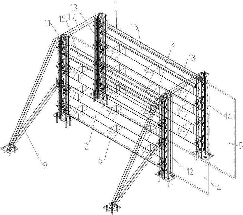
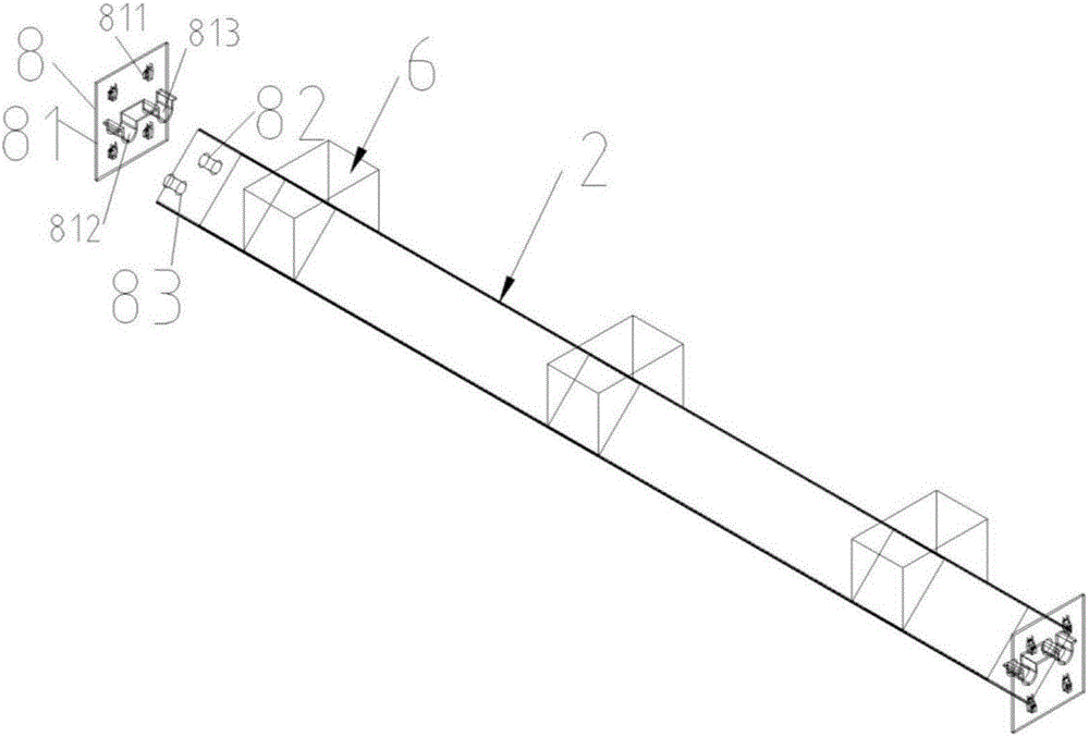
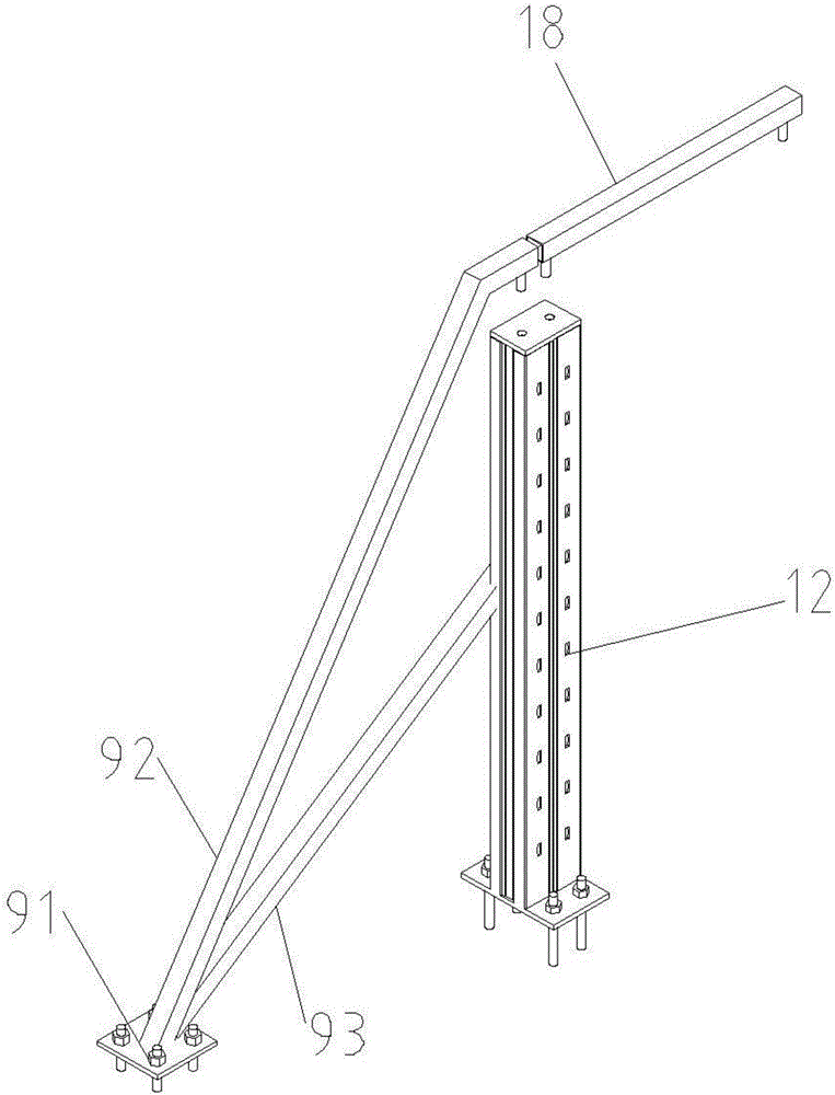
[0031] see figure 1 , figure 2 image 3 and Figure 4 , a batch prefabricated concrete component shared formwork system, which includes: a concrete component shared formwork frame 1, and the concrete component shared formwork frame 1 includes support columns I11, support columns II12, support columns III13, and support columns IV14 in a rectangular array, The high position between the laterally adjacent supporting columns I11 and II12 is connected as a whole through the detachable connecting beam I15, and the high position between the horizontally adjacent supporting columns III13 and supporting column IV14 is connected through the detachable connecting beam II16 Connected as a whole, the top between vertically adjacent supporting columns I11 and sup...


PUM


Abstract

The invention discloses a sharing formwork system for batch prefabricated concrete members. The sharing formwork system comprises at least one concrete member sharing formwork frame, at least one cross beam I arranged between a lateral support upright I and a lateral support upright II of the concrete member sharing formwork frame, at least one cross beam II arranged between a lateral support upright III and a lateral support upright IV, a formwork I arranged between the lateral support upright I and the lateral support upright II and a formwork II arranged between the support upright III and the support upright IV which are laterally adjacent, wherein wooden cushion blocks are arranged on the cross beam I and the cross beam II respectively; reinforcement cages to be cast with concrete are arranged in cavities between the formwork I and the formwork II which are fixed with the wooden cushion blocks. The sharing formwork system for the batch prefabricated concrete members has the beneficial effects as follows: after concrete casting is finished and then certain strength is reached, the concrete member sharing formwork frame can be dismounted in advance while concrete beams are left in situ, and turnover of a formwork support system is accelerated greatly; meanwhile, the formwork use quantity is greatly reduced, and the sharing formwork system has significant economic benefit.

Description

technical field [0001] The invention relates to the field of industrial and civil buildings, in particular to a shared formwork system for batch prefabricated concrete components. Background technique [0002] The traditional building formwork system usually adopts on-site support to complete the pouring according to the actual conditions of the project site. Some formwork supports are fixed in the soft soil mound on site, and the construction accuracy is not high. When concrete is poured, mold runout and grout leakage are prone to occur. In terms of construction technology, the traditional formwork system requires a large number of wooden squares and scaffolding tubes as the supporting components of the formwork system when pouring concrete, and each formwork structure is formed independently, so it is impossible to form the formwork shared between components; on-site construction In terms of environment, a large number of formwork support members such as wooden squares and...

Claims


Application Information

Patent Timeline
Patent Type & Authority Applications(China)
IPC IPC(8): B28B7/00B28B7/24
CPCB28B7/0002B28B7/0029B28B7/24
Inventor 陈明
Owner SHANGHAI OPEN STEEL JOIST
Why Eureka
Try Eureka