Automatic ash removal device for flue of aluminum electrolysis cell

A technology of automatic ash removal and aluminum electrolytic cell, which is applied in the field of automatic ash removal device for flue, can solve the problems of heavy cleaning workload of flue ash accumulation, effective utilization of tail gas in shelling and feeding system, etc., and achieves improved energy utilization rate, Avoid flying loss and enhance the cleaning effect

Inactive Publication Date: 2016-11-23
沈阳铝镁科技有限公司
View PDF6 Cites 1 Cited by
  • Summary
  • Abstract
  • Description
  • Claims
  • Application Information

AI Technical Summary

Problems solved by technology

[0005] In order to solve the above technical problems, the present invention provides an automatic ash cleaning device for the flue of an aluminum electrolytic cell, the purpose of which is to solve the problems of a large amount of dust cleaning work in the flue and effective utilization of the tail gas of the shelling and cutting system

Method used


Image

  • Automatic ash removal device for flue of aluminum electrolysis cell
  • Automatic ash removal device for flue of aluminum electrolysis cell
  • Automatic ash removal device for flue of aluminum electrolysis cell

Examples


Embodiment 1

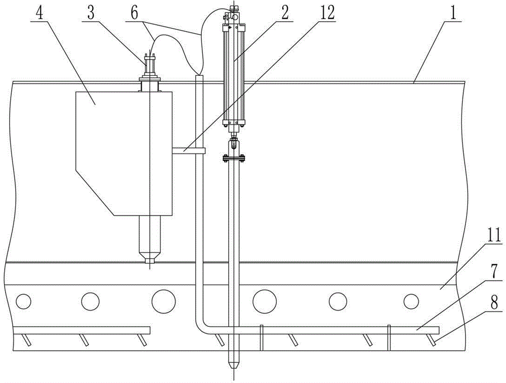
[0028] Such as figure 1 As shown, the automatic dust removal device for the flue of an aluminum electrolytic cell includes a shelling cylinder 2 and a constant volume feeder 3. The cleaning pipe 7 in the road is connected. The cleaning pipe 7 is provided with a blowing pipe 8 . The flue includes an upper flue 5 and a lower flue 11. In the present embodiment, the dust removal pipe 7 is arranged in the lower flue 11 . The number of blowing pipes 8 welded on each cleaning pipe 7 is 2 to 20. The diameter of the blowing pipe is 10-100 mm, and the diameter of the blowing pipe in this embodiment is 30 mm. The diameter range of the dust removal pipe is 20-200 mm, and the diameter of the dust removal pipe 7 in this embodiment is 40 mm. The ash removal pipe 7 is fixed on the material box 4 and the lower flue 11 by a bracket 12 .

Embodiment 2

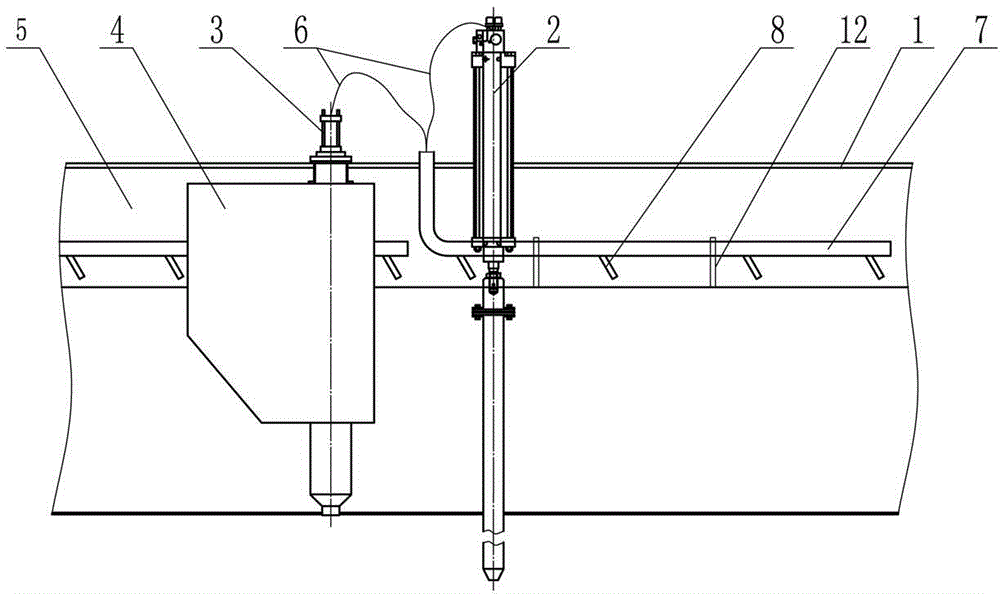
[0030] Such as figure 2 As shown, the dust removal pipe 7 in Embodiment 1 is arranged in the upper flue 5 , and the dust removal pipe 7 is fixed on the upper flue 5 through the bracket 12 . Others are with embodiment 1.

Embodiment 3

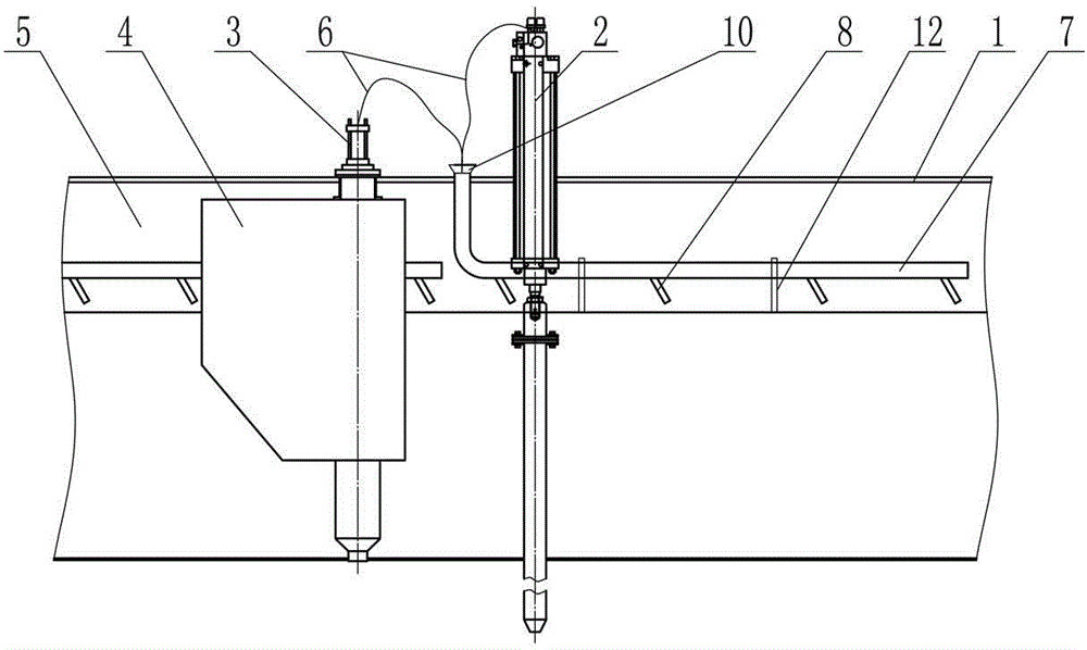
[0032] Such as image 3 As shown, the end of the ash inlet end of the ash removal pipe 7 in Embodiment 2 is provided with a trumpet-shaped drainage horn pipe 10 . Flexible pipe 6 is inserted in the drainage bell pipe 10. The diameter of the spray pipe in this embodiment is 50mm. The diameter range of the dust removal pipe is 20-200 mm, and the diameter of the dust removal pipe 7 in this embodiment is 80 mm. The pipe diameter ranges of the upper and lower mouths of the drainage trumpet pipe 10 are 40-300 mm and 20-200 mm respectively, and the height ranges are 30-300 mm. Drainage trumpet pipe 10 is welded or bolted to soot cleaning pipe 7. In this embodiment, the ash removal pipe 7 is arranged in the upper flue 5 . Others are with embodiment 1.


PUM

PropertyMeasurementUnit
lengthaaaaaaaaaa
diameteraaaaaaaaaa
heightaaaaaaaaaa

Abstract

The invention relates to an automatic ash removal device for a flue, in particular to an automatic ash removal device for a flue of an aluminum electrolysis cell. By the adoption of the ash removal device, ash removal for the gas collection flue can be achieved by means of tail gas of a crust-breaking and feeding system used for the aluminum electrolysis cell. The automatic ash removal device for the flue of the aluminum electrolysis cell comprises a crust-breaking cylinder and a constant-volume feeder. An exhaust vent of the crust-breaking cylinder and an exhaust vent of the constant-volume feeder are connected with an ash removal pipe arranged in the flue through hoses correspondingly. By the adoption of the automatic ash removal device for the flue of the aluminum electrolysis cell, automatic ash removal for the gas collection flue can be achieved by effectively utilizing the tail gas of the crust-breaking and feeding system, the energy utilization rate is increased, the gas collection effect of the flue and the sealing efficiency of the aluminum electrolysis cell are effectively guaranteed, the work of manual removal of accumulated ash in the flue is completely eliminated, and flying loss of aluminum oxide raw materials in the manual ash removal process is avoided.

Description

technical field [0001] The present invention patents an automatic ash removal device for flue, in particular to an automatic ash removal device for aluminum electrolytic cell flue that realizes gas collection flue exhaust gas from shelling and feeding system for aluminum electrolytic cell. Background technique [0002] During the production and operation of aluminum electrolytic cells, two problems are generally encountered. One is that the dust accumulation in the gas collecting flue is difficult to clean up, and the other is how to deal with the exhaust gas of the compressed air used in the shelling and feeding system. [0003] Regardless of whether the electrolytic cell adopts the upper flue gas collection structure or the lower flue gas collection structure, the dust accumulation in the flue is always an inevitable problem, and seriously affects the gas collection effect of the flue. Some aluminum factories use compressed air from the electrolysis workshop to regularly b...

Claims


Application Information

Patent Timeline
Patent Type & Authority Applications(China)
IPC IPC(8): C25C3/22
Inventor 王富强张国斌赵冰洋曹得志丁大勇李斌
Owner 沈阳铝镁科技有限公司
Why Eureka
Try Eureka