
Bolt support control production zone identification method

An identification method and rod string technology, which are used in earth-moving drilling, production of fluids, wellbore/well components, etc., can solve the problem of inability to intuitively judge the situation of layer changes on the spot, the inability to realize the situation of downhole switch layer changes, and the inability to realize layer changes. It can achieve the effect of facilitating transportation and on-site operation, improving the reliability of layer changing, and simplifying the structure of the construction pipe string.

Inactive Publication Date: 2016-11-23
CHINA PETROLEUM & CHEM CORP +1
View PDF3 Cites 2 Cited by
  • Summary
  • Abstract
  • Description
  • Claims
  • Application Information

AI Technical Summary

Problems solved by technology

This technology cannot intuitively judge the situation of layer change on site, and professional technicians need to analyze the test results to identify the situation of the downhole layer change switch, and the operation is complicated
The patent No. CN101906948 A is the non-moving string layer-changing oil production technology, and a layered production converter of the oil well pump has been developed. The impact force when the plunger of the oil pump hits the pump twice can realize the layered production, but it cannot be realized. Visually display the layer change status of the downhole switch on the ground
The patent number is CN104213884 A. The sucker rod-controlled non-moving string layer-changing oil production method uses the sucker rod on the surface of the pumping well to control the downhole pump to exploit two intervals in rotation, and it is also impossible to realize the intuitive identification of the downhole switch on the ground. Layer change

Method used


Image

  • Bolt support control production zone identification method
  • Bolt support control production zone identification method
  • Bolt support control production zone identification method

Examples


Embodiment Construction

[0022] The detailed description and technical content of the present invention are described below with the accompanying drawings, but the accompanying drawings are only provided for reference and description, and are not intended to limit the present invention.

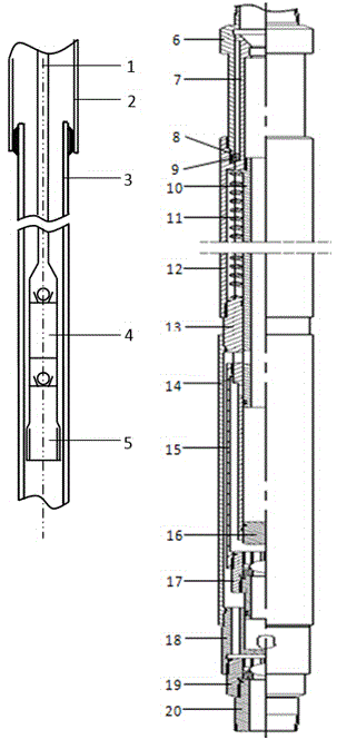
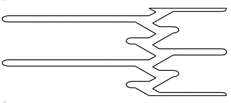
[0023] Refer to attached Figure 1-4 , a method for identifying production layers controlled by a pole column, comprising a pump barrel and a track control mechanism, a flow diversion control mechanism, and an upper fixed Verl production system arranged sequentially from top to bottom at the lower part of the pump barrel, and the outer side of the upper fixed Verl production system is A lower fixed Vers production system is provided, and the diversion control mechanism can communicate with the upper fixed Vers production system and the lower fixed Vers production system respectively through the control of the track control mechanism. The lower end of the pump cylinder is connected to the connector 6, and the inside o...


PUM


Abstract

The invention discloses a bolt support control production zone identification method. At the initial stage, a fixed valve channel of a zone exchange oil production pump is opened, and a pump barrel plunger realizes swabbing production; an oil pumping rod is dropped during zone exchange; the oil pumping rod is firstly connected with an underground zone exchange pump, and then dropped; the oil pumping rod drives the plunger to go downwards to press a reversing rail control mechanism; the reversing rail control mechanism drives a shunt control mechanism to be located at two different high points indirectly; the shunt control mechanism can respectively communicate with an upper fixed valve production system and a lower fixed valve production system under the control of a rail control mechanism, so that the reversing condition of an underground switch can be directly judged according to different lengths of the oil pumping rod remained on the ground at two pump collisions. The bolt support control production zone identification method can directly judge a production zone and a zone exchange condition of an underground zone exchange oil production pipe type pump at the site according to different remained lengths of a polish rod at two pump collisions, so that the reliability and the visibility of zone exchange production are greatly improved, and the possibility that the zone exchange condition can only be checked by production due to the phenomenon that the production zone and the zone exchange condition in a well cannot be directly judged on the ground is avoided.

Description

technical field [0001] The invention relates to the layered oil testing technology in the petroleum industry, in particular to a rod string control production layer identification method. Background technique [0002] At present, most of the oil wells in my country have multiple layers, and oil wells with large interlayer differences and unbalanced interlayer production need to use layered oil production process strings for layered production. The integral layered oil production process string has the advantages of simple construction and reliable sealing. It has been widely used in major oil fields, but it can only realize the sealing of one layer to produce the other layer. When changing layers, the original production pipe must be pulled out. Column, re-running into the production string, the workload is heavy. After the conventional layer change method, the ground cannot be displayed visually, and the layer change status of the downhole switch cannot be judged. The prod...

Claims


Application Information

Patent Timeline
IPC IPC(8): E21B43/14
Inventor 古光明孟永程正全张雷姜国良宋清新闫文文戴超郭海滨杨峰费秀英马骁祁辛华
Owner CHINA PETROLEUM & CHEM CORP
Learn More