Fault detecting and processing method for continuous variable valve lift mechanism

A fault handling method and valve lift technology, applied in electrical control, mechanical equipment, engine control, etc., can solve problems such as wrong judgment results, motor heating, burning, etc.

Active Publication Date: 2016-11-23
GREAT WALL MOTOR CO LTD
View PDF6 Cites 7 Cited by
  • Summary
  • Abstract
  • Description
  • Claims
  • Application Information

AI Technical Summary

Problems solved by technology

[0004] However, in the above position determination method, when the above predetermined time is short, the motor shaft does not get stuck and the actual lift of the valve does not reach the target lift, and it is still determined that the motor is locked, thus obtaining a wrong Judgment result; therefore, in order to obtain an accurate judgment result, the above-mentioned predetermined time is usually set longer, and it must exceed the predetermined time before it can be judged whether the motor is blocked. Dealing with motor stalling, resulting in serious heating of the motor, or even being burned

Method used


Image

  • Fault detecting and processing method for continuous variable valve lift mechanism
  • Fault detecting and processing method for continuous variable valve lift mechanism
  • Fault detecting and processing method for continuous variable valve lift mechanism

Examples


Embodiment 1

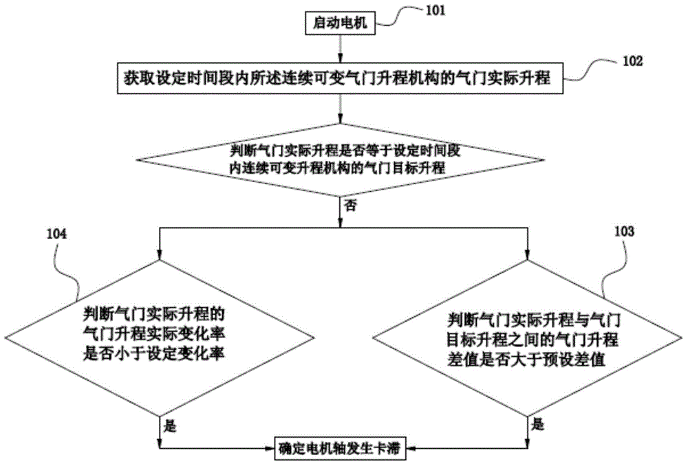
[0044] This embodiment provides a fault detection method for a continuously variable valve lift mechanism, wherein the continuously variable valve lift mechanism includes a control unit, a motor, a valve and a sensor for sensing the actual lift of the valve, such as figure 1 As shown, the fault detection method includes:

[0045] Step 101, start the motor;

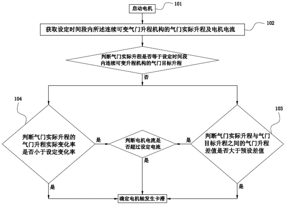
[0046] Step 102, obtaining the actual valve lift of the continuously variable valve lift mechanism within a set time period;

[0047]Step 103, when the actual valve lift is not equal to the target valve lift of the continuously variable valve lift mechanism within the set time period, and the valve lift difference between the actual valve lift and the valve target lift is greater than the preset difference value to determine that the motor shaft of the motor is stuck; or

[0048] Step 104, when the actual valve lift is not equal to the target valve lift of the continuously variable valve lift mechanism within the set tim...

Embodiment 2

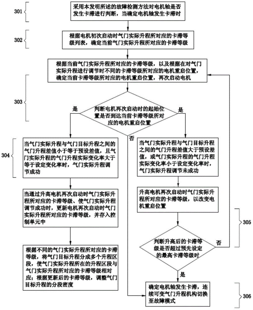
[0053] This embodiment is a method for troubleshooting a continuously variable valve lift mechanism, such as image 3 As shown, the troubleshooting methods include:

[0054] Step 301 , using the fault detection method in the first embodiment above to judge whether the motor shaft is stuck; when it is determined that the motor shaft is stuck, execute step 302 . For the detection method of whether the motor shaft is stuck, please refer to the first embodiment above, which will not be repeated here.

[0055] Step 302 , according to the sticking level list corresponding to the actual valve lift when the electric motor is started for the first time, determine the sticking level corresponding to the current actual valve lift.

[0056] Step 303, according to the sticking level corresponding to the current actual valve lift, and according to the motor restart position corresponding to different sticking levels when the actual valve lift is adjusted, determine the motor restart positi...


PUM


Abstract

The invention provides a fault detecting and processing method for a continuous variable valve lift mechanism, relates to the technical field of engines, and is used for discovering and processing the problem of motor stalling. The fault detecting method comprises the steps that a motor is started, and a practical valve lift of the continuous variable valve lift mechanism in a preset time period is obtained; and when the practical valve lift is unequal to a target valve lift in the preset time period, and the valve lift difference between the practical valve lift and the target valve lift is greater than a preset difference, or when the practical valve lift is unequal to the target valve lift in the preset time period, and the practical valve lift changing rate of the practical valve lift is smaller than a preset changing rate, motor shaft seizing is confirmed. The fault detecting and processing method is used for judging whether motor shaft seizing occurs, so that motor stalling is eliminated in time.

Description

technical field [0001] The invention relates to the technical field of engines, in particular to a fault detection and processing method of a continuously variable valve lift mechanism. Background technique [0002] In order to cope with the lack of resources and environmental pollution, countries around the world have set off a wave of energy saving and emission reduction. For example, automobile engines adopt continuously variable valve lift mechanisms. The continuously variable valve lift mechanism means that under the drive of the motor, the valve lift position adjustment mechanism (for example, worm gear / worm) adjusts the rotation angle of the eccentric shaft to change the valve lift, reduce the pumping loss of the engine throttle, and improve Fuel economy, reduce exhaust emissions, achieve the purpose of energy saving and emission reduction. Among them, the motor is the core actuator of the continuously variable valve lift mechanism. During the operation of the motor,...

Claims


Application Information

Patent Timeline
Patent Type & Authority Applications(China)
IPC IPC(8): F02D41/22
Inventor 王志伟田宪凯于浩然
Owner GREAT WALL MOTOR CO LTD
Why Eureka
Try Eureka