Steel bar connecting piece, connecting method, connecting connector and special extrusion die

A technology for extruding dies and connecting joints, which is applied in the direction of connecting components, rods, building components, etc. It can solve the problems of large overlapping areas, large overlapping lengths, and difficulty in construction on site, so as to achieve good connection strength and prevent The effect of sleeve breakage

Active Publication Date: 2016-11-23
刘祥锦
View PDF7 Cites 9 Cited by
  • Summary
  • Abstract
  • Description
  • Claims
  • Application Information

AI Technical Summary

Problems solved by technology

[0006] 1. The disadvantages of using (1) steel bar binding and lap joints are: the length of the lap joint is large, the amount of post-cast concrete on site is large, the proportion of prefabricated parts is greatly reduced, and the prefabrication rate is reduced; a large number of formwork is also used on site, which cannot give full play to the advantages of assembly , the use of staggered laps has a larger lap area and is more obviously not suitable for industrialization needs
[0007] 2. The disadvantage of using (2) steel bar welding is that the on-site welded steel bar cannot meet the requirements of a first-class weld seam. In addition, due to the heat treatment of the steel bar by welding, it is also difficult to meet the I and II joint standards for building seismic steel bar connections. "Reinforcement Machinery Connection Technical Regulations JGJ107-2010》
[0008] 3. The disadvantage of using (3) steel bar sleeve connection is that the steel bar requires accurate alignment, and the connected steel bar is required to be aligned and inserted into the sleeve. Due to the production error of the steel bar and the impact of the transportation process, the reserved steel bar will be bent. Therefore, each steel bar must be inspected and straightened, and the alignment of the steel bar is completed in the air during the hoisting process, which brings great difficulty to the construction site and the construction efficiency is not high
[0009] 4. The current reinforcement connection technology does not solve the prefabricated component reinforcement connection well. For example, it is difficult to realize the I-level joint connection between the steel bars at both ends of the prefabricated horizontal components of the prefabricated building and the reserved steel bars on both sides of the installed components at the same time. This kind of connection mostly adopts mechanical connection at one end and lap joint at the other end. The disadvantage is that the non-prefabricated section reserved for lap joint is long, resulting in low prefabrication rate

Method used


Image

  • Steel bar connecting piece, connecting method, connecting connector and special extrusion die
  • Steel bar connecting piece, connecting method, connecting connector and special extrusion die
  • Steel bar connecting piece, connecting method, connecting connector and special extrusion die

Examples


Embodiment 2

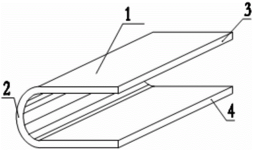
[0059] see image 3 , this embodiment is the second embodiment of the connector 1 for steel bar connection of the present invention, the difference between the connector 1 of this embodiment and the embodiment 1 is: the first steel plate segment 3 and The second steel plate section 4 is connected with an additional arc-shaped steel plate section 2-1 at the end opposite to the arc-shaped steel plate section 2, and the arc surface of the additional arc-shaped steel plate section 2-1 is connected to the first steel plate Segment 3 is tangent to second steel plate segment 4 . The cross-section of the connecting piece 1 in this embodiment is in the shape of an oblong shape similar to a standard runway in a playground.

specific Embodiment approach

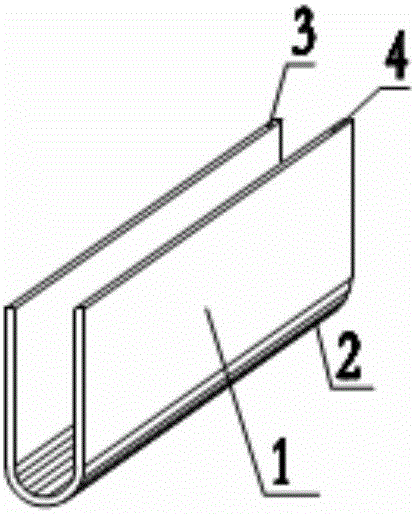
[0061] see Figure 4 with Figure 5 , this embodiment is a specific implementation of the connection method for steel bar connection realized by the connector 1 described in the application embodiment 1 of the present invention, and the connection method includes the following steps:

[0062] (1) The connecting ends of the reinforcing bar A5 and the reinforcing bar B6 to be connected are brought together in parallel to form an overlapping overlapping section, and the length of the overlapping overlapping section is greater than the length of the connector 1;

[0063] (2) Buckle the connecting piece 1 on the overlapping section of steel bar A5 and steel bar B6, and let one of the steel bars A5 reach the arc-shaped bottom of the connecting piece 1 and make it close (see Figure 4 );

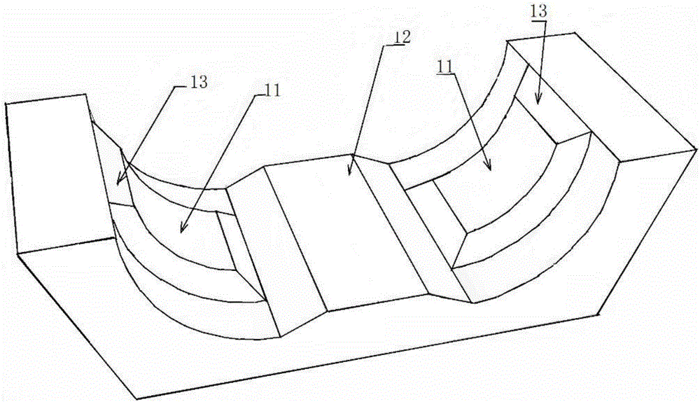
[0064] (3) Cover the special extrusion die installed on the extruding device outside the connector 1, and the extruding device adopts existing conventional equipment;

[0065] (4) Use extrusion ...

Embodiment 4

[0067] see Figure 6-Figure 8 , this embodiment is the first specific implementation of the steel bar connection joint obtained by applying the connection method described in Example 3 of the present invention, and the joint includes the connection of steel bar A5 and steel bar B6 that are close together in parallel to form overlapping overlapping sections end and the connecting piece 1 wrapped on the connecting end of the steel bar A5 and the steel bar B6, the inner surface of the connecting piece 1 and the convex rib on the surface of the steel bar tightly bite together, and the contact surface between the steel bar A5 and the steel bar B6 is pressed against each other Tight and bite.

[0068] The outer surface of the connecting piece 1 is provided with circumferential grooves 7 , and the circumferential grooves 7 are in multiple groups, distributed along the axial direction of the connecting piece 1 , and surround the whole connecting piece 1 .


PUM

PropertyMeasurementUnit
angleaaaaaaaaaa

Abstract

The invention discloses a steel bar connecting piece, a connecting method, a connecting connector and a special extrusion die. The connecting piece comprises an arc steel plate section, a first steel plate section and a second steel plate section, wherein the first steel plate section and the second steel plate section are connected to two arc edges of the arc steel plate section correspondingly. The connecting connector comprises connecting ends of a steel bar A and a steel bar B and connecting pieces wrapping the connecting ends of the steel bar A and the steel bar B, wherein the connecting ends lean against each other in parallel, and a lap joint overlapping section is formed; and the inner surfaces of the connecting pieces and protruding ribs on the surfaces of the steel bars are closely engaged together, and contact faces between the steel bar A and the steel bar B are pressed mutually and engaged. The steel bar connecting piece, the connecting method, the connecting connector and the special extrusion die are supplementation of the steel bar connecting technology, and application of the steel bar connecting piece, the connecting method, the connecting connector and the special extrusion die to connection of the steel bars has the beneficial effects that safe reliability of high connecting strength is achieved, the economical efficiency of low construction difficulty and time and labor saving during operation is achieved, and the application range is wide.

Description

technical field [0001] The invention relates to a steel bar connecting device and a method for building construction technology, in particular to a connecting piece for connecting steel bars, a connecting method, a connecting joint and a special extrusion die. Background technique [0002] At present, the country has proposed the future development direction of the construction industry of smart cities, green buildings and construction industrialization; and proposed to use about 10 years to make the proportion of prefabricated buildings account for 30% of new buildings; construction industrialization has become an important topic for current development. The development industry encouraged and supported by policies. [0003] At present, in the process of the construction industry transitioning from traditional on-site construction to industrial production, the development of new technical structural systems and large-scale transportation and hoisting equipment in constructi...

Claims


Application Information

Patent Timeline
Patent Type & Authority Applications(China)
IPC IPC(8): F16B2/06F16B7/04E04C5/16B21F15/06
CPCB21F15/06E04C5/167F16B2/06F16B7/0433
Inventor 刘祥锦刘俊彦
Owner 刘祥锦
Why Eureka
Try Eureka