
Method for measuring liquid viscosity coefficient through spring ball system

A technology of viscosity coefficient and small balls, which is applied in the field of physical experiments, can solve problems such as the inability to effectively guarantee the drop angle and posture of the needle drop, the deflection in the vertical direction of the needle drop, and the complexity of instruments and equipment, and achieve a convenient and fast measurement method. The instrument is simple and the effect of improving the experimental efficiency

Inactive Publication Date: 2016-11-23
QIQIHAR UNIVERSITY
View PDF9 Cites 3 Cited by
  • Summary
  • Abstract
  • Description
  • Claims
  • Application Information

AI Technical Summary

Problems solved by technology

However, the equipment of the needle drop method is complicated, and because before launching, the permanent magnet of the transmitter and the falling needle are magnetically attracted, and the upper end of the falling needle is spherical, which cannot be completely sealed with the horizontal end surface of the transmitter magnet, causing the needle to fall before launching. There is a deflection angle with the vertical direction, and the gravity of the falling needle is much smaller than the magnetic force, so it cannot be corrected by gravity
When launching, the transmitter forcibly distances itself from the falling needle, causing the falling needle to fall under gravity. At this moment, the entire instrument is under force, which interferes with the falling direction of the falling needle, and cannot effectively guarantee the falling angle and posture of the falling needle.

Method used


Image

  • Method for measuring liquid viscosity coefficient through spring ball system
  • Method for measuring liquid viscosity coefficient through spring ball system
  • Method for measuring liquid viscosity coefficient through spring ball system

Examples


Embodiment Construction

[0044] The present invention will be further described below in conjunction with the accompanying drawings and a specific embodiment.

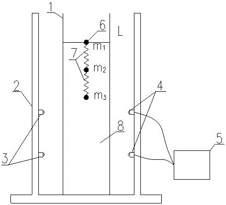
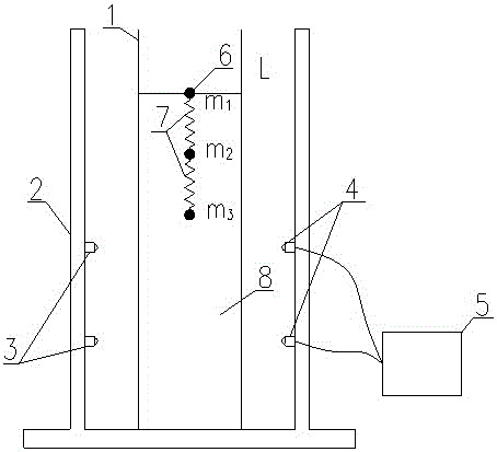
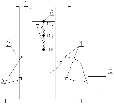
[0045] Such as figure 1 As shown, the spring ball system that the method for measuring the viscosity coefficient of liquid described in this embodiment relies on consists of three small balls 6

[0046] It is composed of two springs 7 cross-connected. The three small balls 6 have smooth surfaces and similar diameters, and the diameters from top to bottom are d 1 、d 2 、d 3 , with a mass of m 1 、m2 、m 3 , and m 1 2 3 ; The spring 7 is a light and uniform spring, and the lengths of the two springs 7 are close to each other, and the lengths from the top to the bottom are L respectively 1 , L 2 .

[0047] Such as figure 2 and image 3 As shown, it is the photoelectric falling ball viscometer used in this embodiment. The measuring cylinder 1 is a plexiglass measuring cylinder with an experimental liquid 8 inside. Two lasers 3 are install...


PUM


Abstract

The invention discloses a method for measuring the liquid viscosity coefficient through a spring ball system. According to the method, balls with close diameters and gradually increased densities are connected together through light springs with close lengths and rigidities to form the spring ball system. The system is soaked in experiment liquid with viscosity coefficient to be measured, forward releasing and backward releasing are conducted at the center of the liquid surface, the falling time of the whole spring ball system passing through two measurement points in to-be-measured liquid is measured, and the viscosity coefficient of the liquid is obtained by analyzing the balance relation of the internal action and the external load of the spring ball system. Compared with an existing method, the method has the advantages that the method is convenient and rapid to implement, whether balls reach a constant-speed falling stage is easily judged, the falling form of the system can be easily controlled, required instruments and equipment are simple, and the method is suitable for liquid viscosity coefficient theoretical research and also suitable for physics experiment teaching.

Description

technical field [0001] The invention relates to a physical experiment method, in particular to a method for measuring the viscosity coefficient of a liquid by using a small spring ball system. Background technique [0002] The measurement experiment of liquid viscosity coefficient is one of the important confirmatory experiments in university physics. The measurement methods mainly include falling ball method, falling needle method, capillary method and rotation method. Intuitive, easy for students to understand the physical meaning of liquid viscosity coefficient, and become a widely used measurement method of liquid viscosity coefficient. [0003] The advantage of the falling ball method is that it is easy to operate, but the disadvantage is that the error of the measurement result is relatively large. According to the research in the literature "Research on the Error of Measuring Liquid Viscosity Coefficient by Falling Ball Method" ("Laboratory Science", Volume 17, Issue...

Claims


Application Information

Patent Timeline
IPC IPC(8): G01N11/12G09B23/08
CPCG01N11/12G09B23/08
Inventor 刘相梅
Owner QIQIHAR UNIVERSITY
Learn More