Mechanical device for sun tracking and control system and method thereof

A solar tracking and mechanical technology, applied in the field of solar tracking technology research, can solve the problems of high device material performance and installation requirements, unreasonable power matching, increasing the driving force of the bottom shaft, etc., so that the working principle is simple and easy to understand and the tracking range Large, avoid the effect of cumulative error

Inactive Publication Date: 2016-11-23
JIANGSU UNIV
View PDF7 Cites 2 Cited by
  • Summary
  • Abstract
  • Description
  • Claims
  • Application Information

AI Technical Summary

Problems solved by technology

However, due to unstable performance and extremely high cost in China, it has not been popularized and put into production. For example, the patented "sun tracking device, publication number: CN103676968A, has high dual-axis tracking accuracy, but it is also supported by a single arm, with poor wind resistance and excessive bearing of components. prone to metal damage
[0004] Optical fiber light guide systems are mostly based on two-axis tracking mechanical platforms, but the current two-axis tracking mechanical platforms have the problem of being top-heavy. Increasing the driving force of the bottom shaft will easily lead to unreasonable power matching and excessive component bearing, etc. The performance and installation requirements of the device materials are relatively high, and the later maintenance is difficult and costly, and the service life is short

Method used


Image

  • Mechanical device for sun tracking and control system and method thereof
  • Mechanical device for sun tracking and control system and method thereof
  • Mechanical device for sun tracking and control system and method thereof

Examples


Embodiment Construction

[0037] The present invention will be described in further detail below in conjunction with the accompanying drawings and specific embodiments, but the protection scope of the present invention is not limited thereto.

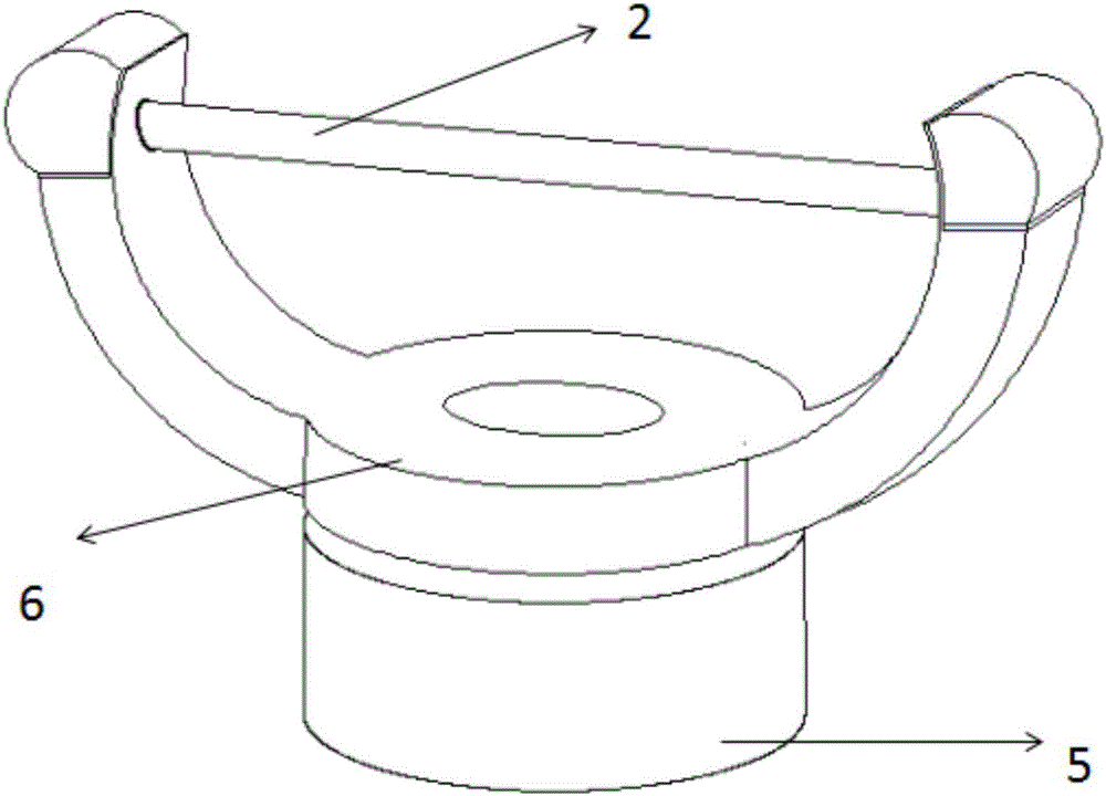
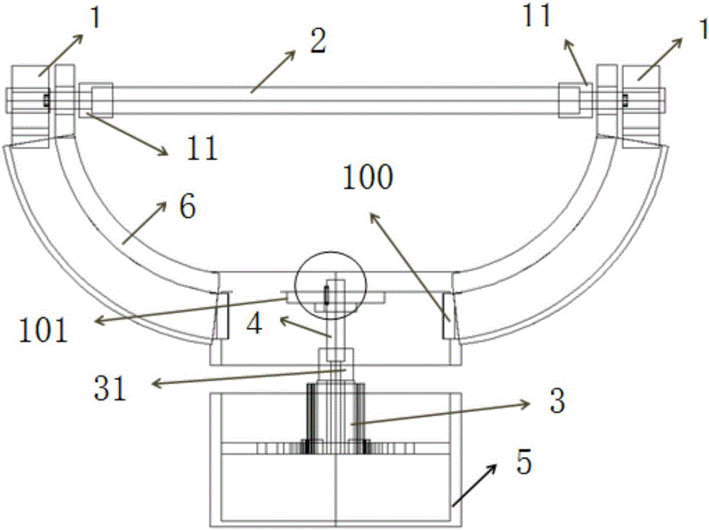
[0038] figure 1 with figure 2 Shown is an embodiment of the mechanical device for sun tracking of the present invention, the mechanical platform device for sun tracking includes two height and orientation motors 1, output rotation shaft 2, chassis motor 3, connecting shaft 4. Chassis 5, U-shaped upper end cover 6 and control module.

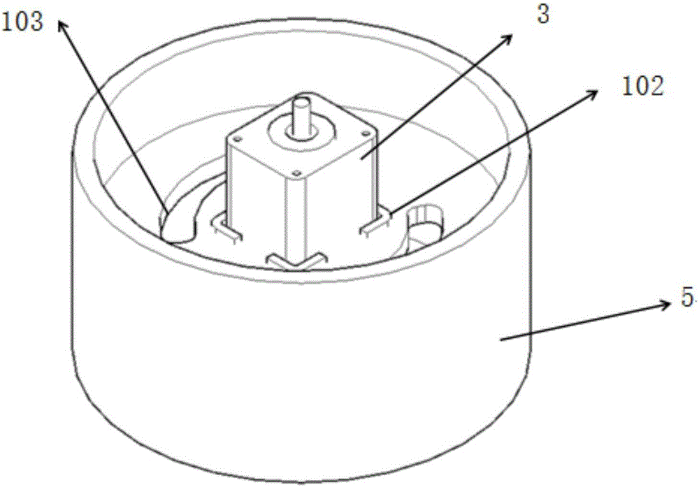
[0039] Such as image 3As shown, the chassis 5 is cylindrical, and the chassis 5 is divided into upper and lower layers by a partition, and a motor fixing groove 102 is arranged at the center of the upper layer, and the chassis motor 3 is installed in the motor fixing groove 102; the control module Placed in the lower layer of chassis 5. The chassis motor 3 is connected to one end of the connecting shaft 4 through a chassis mo...


PUM


Abstract

The invention provides a mechanical device for solar tracking, a control system of the mechanical device for the solar tracking and a control method of the control system of the mechanical device for the solar tracking. The mechanical device for the solar tracking comprises two altitude-azimuth motors, an output rotating shaft, a chassis motor, a connecting shaft, a chassis, a U-shaped upper end cover and a control module; the chassis motor is fixed in the chassis, and connected with the connecting shaft, the connecting shaft is connected with the U-shaped upper end cover, and the two altitude-azimuth motors are respectively arranged on two arms of the U-shaped upper end cover and fixed to the surfaces of the arms, and respectively connected with the output rotating shaft; the chassis motor drives to drive the U-shaped upper end cover to carry out 360-azimuth rotation in a large area; furthermore, the two altitude-azimuth motors are synchronously rotated symmetrically in different directions, so that the output rotating shaft rotates in an elevation angle of 360 degrees, and can revolve by following sunlight in a large range in the three-dimensional space; the mechanical device for the solar tracking disclosed by the invention can effectively solve the problem that a solar-tracking support frame is top-heavy, and has simple structure, small mechanical clearances, wide tracking range, convenience in maintaining mechanical linkage, low cost and easy automatic control.

Description

technical field [0001] The invention belongs to the field of sun tracking technology research, in particular to a mechanical device, control system and method for sun tracking. Background technique [0002] The development of new energy is an important part of the national sustainable development strategy of various governments, especially the development and utilization of solar energy. Solar energy is an emerging renewable energy source, an inexhaustible ideal energy source. But at present, the utilization of solar energy is not very popular, and there are still many problems in using solar energy to generate electricity, such as high cost and low conversion efficiency. [0003] The solar automatic tracking system can greatly improve the utilization rate of solar energy. The solar automatic tracking system generally has a single-axis type, a double-axis type and a three-axis type. Although the single-axis tracking has a simple structure, it can only track at one angle. Du...

Claims


Application Information

Patent Timeline
Patent Type & Authority Applications(China)
IPC IPC(8): G05D3/12
CPCG05D3/12
Inventor 张丽陈明阳叶云霞刘丕丕曹国栋岳震
Owner JIANGSU UNIV
Why Eureka
Try Eureka