Supercharge Your Innovation With Domain-Expert AI Agents!

Buffer, data driving circuit and display device

A technology for data driving circuits and buffers, applied in the field of buffers, can solve the problems of overheating, high circuit power consumption, and increased circuit power consumption, and achieve the effects of reducing power consumption, reducing power loss, and avoiding overheating

Active Publication Date: 2016-11-23
王建国
View PDF5 Cites 2 Cited by
  • Summary
  • Abstract
  • Description
  • Claims
  • Application Information

AI Technical Summary

Problems solved by technology

From the above, it can be seen that the power consumed by the second gamma buffer 12 and the third gamma buffer 13 is much larger than that of the first gamma buffer 11 and the fourth gamma buffer 14, thus causing power consumption of the entire circuit Substantial increase
In addition, due to the large power consumption of the known circuit, there will be a problem of overheating

Method used


Image

  • Buffer, data driving circuit and display device
  • Buffer, data driving circuit and display device
  • Buffer, data driving circuit and display device

Examples


Embodiment Construction

[0029] A buffer, a data driving circuit and a display device according to preferred embodiments of the present invention will be described below with reference to related drawings, wherein the same components will be described with the same reference symbols.

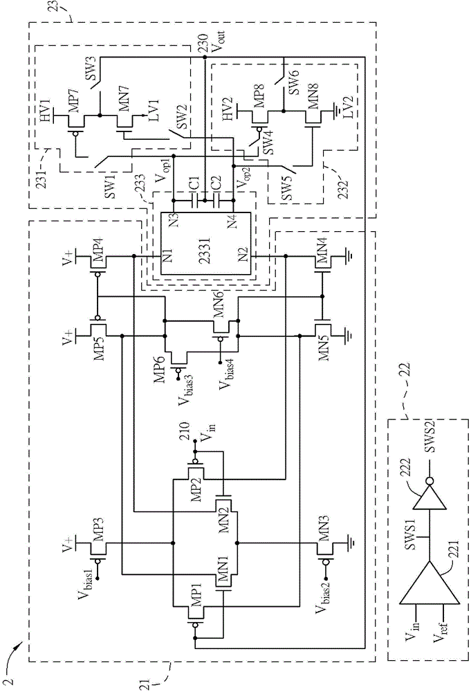
[0030] image 3 It is a schematic circuit diagram of a buffer in a preferred embodiment of the present invention. For the convenience of description, in the following description, the terminal point facing upward of each transistor in the figure is the first terminal, and the terminal point facing downward is the second terminal. Wherein, the first terminal or the second terminal may be a source terminal or a drain terminal respectively, which will not be specifically described below. In addition, the control gates or other special-purpose terminals of each component are described separately.

[0031] Please refer to image 3 , the buffer 2 includes an input circuit 21 , a monitoring circuit 22 and an output circuit ...


PUM


Abstract

The invention relates to a buffer. The buffer comprises an input circuit, a monitoring circuit and an output circuit, wherein the input circuit receives an input signal, the monitoring circuit is electrically connected with the input circuit, the input signal is compared with a reference voltage to output a switch signal, the output circuit has a signal output end and is electrically connected with the input circuit and the monitoring circuit, the input signal is taken by the output circuit as an output signal to realize output from the signal output end according to a first high work voltage and a first low work voltage or a second high work voltage and a second low work voltage which are selected according to a state of the switch signal, and the potential of the output signal is between the first high work voltage and the first low work voltage or between the second high work voltage and the second low work voltage.

Description

technical field [0001] The invention relates to a buffer, in particular to a buffer for a data driving circuit. Background technique [0002] Because the liquid crystal material used in the display panel does not match the internal resistance of the data drive circuit, it cannot provide a voltage value that can achieve the appropriate liquid crystal transmittance, resulting in some grayscale signals that cannot approach the ideal gamma curve. Therefore, it is necessary to rely on Correct the gamma voltage to improve the picture image. [0003] figure 1 For the schematic diagram of the data drive circuit and buffer of the known technology, please refer to figure 1 , there are currently some data-driven chips on the market, and their application specifications will include two gamma buffers, and gamma matching resistors RU1, RU2, RU3, RU4, RD1, RD2, RD3, and RD4. Here, four data Take driver chips IC1~IC4 as an example. figure 1 In the above, the input signals of these data...

Claims


Application Information

Patent Timeline
IPC IPC(8): G09G3/36
Inventor 朱志伟
Owner 王建国
Features
  • R&D
  • Intellectual Property
  • Life Sciences
  • Materials
  • Tech Scout
  • Unparalleled Data Quality
  • Higher Quality Content
  • 60% Fewer Hallucinations
Learn More