Resin casting coil dry-type transformer structure and assembling method thereof

A dry-type transformer, resin casting technology, applied in the field of transformers, can solve the problems of insufficient magnetic cross-section, short creepage path, poor strength, etc., and achieve the effects of reducing partial discharge, increasing creepage distance, and ingenious structural design

Active Publication Date: 2016-11-23
鑫大变压器有限公司
View PDF7 Cites 7 Cited by
  • Summary
  • Abstract
  • Description
  • Claims
  • Application Information

AI Technical Summary

Problems solved by technology

The main reasons are: (1) After the dry-type transformer is loaded, unloaded and transported, the high and low voltage resin coils are displaced, and the instantaneous displacement causes a huge pulling or squeezing force, resulting in the above problems
(2) This kind of displacement can also easily cause the relative spacing between the high and low voltage resin coils and the iron core to change, and a short leakage path will appear, which will cause short circuit discharge between the high and low voltage resin coils, and burn out the transformer; (3) This displacement It is also easy to cause the iron core to loosen, resulting in insufficient magnetic cross-section, causing vibration noise and temperature rise, which in turn damages the insulation and reduces the service life of the transformer
[0004] The main reason for the above problems is that the structural design of the existing dry-type transformers is insufficient, mainly in the following points: First, the drawing plate is generally made of steel plate or stainless steel plate, because the drawing plate is long and the intermediate strength is not enough, resulting in the clamping of the iron core. Insufficient tightening force is prone to loose iron core, resulting in large mechanical noise; second, the briquetting block is generally molded by DMC or BMC, and its shape is generally a cuboid, and the creepage path is short, which is easy to cause partial discharge, and its strength is not good; Nails are generally pressed directly on the pressing block, and the force point is only one point, which cannot ensure that the pressure on the pressing block is uniform, which in turn affects the position of the high and low pressure resin coils.

Method used


Image

  • Resin casting coil dry-type transformer structure and assembling method thereof
  • Resin casting coil dry-type transformer structure and assembling method thereof
  • Resin casting coil dry-type transformer structure and assembling method thereof

Examples


Embodiment 1

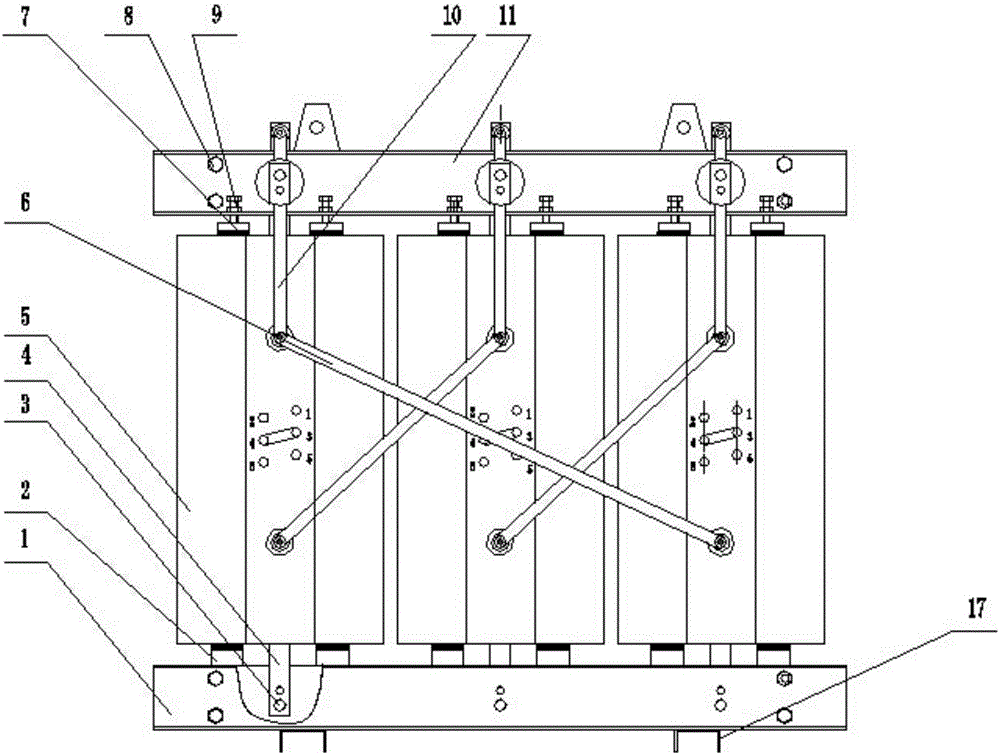
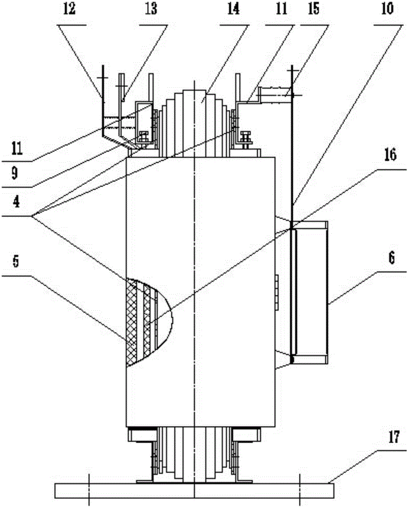
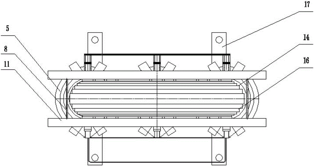
[0041] like Figure 1 to Figure 12 As shown, a resin casting coil dry-type transformer structure includes a transformer body arranged on a base, the base is a supporting channel steel 17, and the transformer body includes an iron core 14, an upper clamp 11, a lower clamp 1, a low-voltage resin coil 16 and the high-voltage resin coil 5. The iron core 14 includes an iron core column, an upper magnetic yoke and a lower magnetic yoke. The iron core 14 is provided with three iron core columns, and the outer circumference of the iron core column is respectively vertically fitted with a high-voltage resin coil 5 and a low-voltage resin coil 16; The bottoms of the high-voltage resin coil 5 and the low-voltage resin coil 16 are seated on the lower clamp 1 through the cushion block and the insert 2, and the tops of the high-voltage resin coil 5 and the low-voltage resin coil 16 are connected to the The upper clamping part is pressed against the pressing plate 18 by the pressing nail 9 o...

Embodiment 2

[0048] A resin casting coil dry-type transformer structure, the structure is as described in Embodiment 1, the difference is that: the upper surface of the pressure plate 18 is provided with a cylindrical pin 1801, the top of the cylindrical pin 1801 is hemispherical, and the bottom end of the pressure nail 9 is set There are blind holes to accommodate cylindrical pins, and the blind ends of the blind holes are also hemispherical. The pressing plate 18 and the pressing nail 9 are connected through a cylindrical pin and a blind hole, and the cylindrical pin is inserted into the blind hole to ensure the stability of the connection between the pressing plate and the pressing nail.

[0049] like Figure 5 As shown, the shape of the through holes at the upper and lower ends of the pull plate 4 is a triangular hole, the pin 3 is a triangular pin, and the mounting holes on the upper and lower clamps are matching triangular holes.

Embodiment 3

[0051] A resin casting coil dry-type transformer structure, the structure is as described in Embodiment 1, the difference is that: the side of the pressure block 701 close to the high voltage resin coil is provided with reinforcing ribs. Adding reinforcing ribs on the side of the pressing block close to the high-voltage resin coil not only increases the strength of the pressing block, but also is more beautiful, and does not increase the bottom section, which will not affect the normal ventilation and heat dissipation of the air duct, and increases the distance between the high-voltage resin coil and the pressing nail. The creepage distance reduces the risk of partial discharge.

[0052] like Image 6 Shown, the shape of the through holes at the upper and lower ends of the pull plate 4 is a square hole, the pin 3 is a square pin (square pin), and the mounting holes on the upper and lower clamps are matching square holes.


PUM


Abstract

The invention relates to a resin casting coil dry-type transformer structure and an assembling method thereof. The resin casting coil dry-type transformer structure comprises a transformer body arranged on a base, wherein the transformer body comprises an iron core, an upper clamping part, a lower clamping part and high-voltage and low-voltage resin coils; the low-voltage resin coil and the high-voltage resin coil sleeve the external circumference of a core column of the iron core respectively; the bottoms of the high-voltage and low-voltage resin coils are mounted on a cushion block and an embedding part of the lower clamping part by piers; a pressing block, an embedding part and a pressing plate are arranged at the top of the high-voltage and low-voltage resin coils and the pressing plate is tightly pressed by rotating a pressing stud through an upper clamping part screw hole, so that the high-voltage and low-voltage resin coils are tightly pressed and fixed; pull plates are arranged on the two sides of the core column of the iron core; and the upper and lower ends of the pull plates are fixedly connected with the upper clamping part and the lower clamping part through pins respectively. With the adoption of the dry-type transformer structure provided by the invention, the stability of the iron core and the coils is enhanced and a displacement phenomenon of the high-voltage and low-voltage resin coils in a transportation process of a transformer can be avoided. The creeping distance is increased through a pressing block reinforcing rib and a partial discharging condition is reduced; and the properties of the transformer are effectively improved.

Description

technical field [0001] The invention relates to a resin casting coil dry-type transformer structure and an assembly method thereof, belonging to the technical field of transformers. Background technique [0002] At present, the dry-type transformer structure usually consists of three high-voltage and low-voltage resin casting coils set on the iron core column, the lower yoke of the iron core is placed on the supporting channel steel, and the four fastening screws of the lower clamp are used to fix and clamp the lower iron core. For the yoke, 3X4 lower pads and inserts are placed on the lower clamp, and the high and low voltage resin casting coils are placed on the lower pads and inserts. The lower clamp and the upper clamp pass through the three pull plates on both sides of the iron core and The pull plate and the lower pin are connected, the upper clamp has 4 lifting rings, the lifting weight of the whole transformer is borne by 6 pull plates, the upper clamp is fixed and c...

Claims


Application Information

Patent Timeline
Patent Type & Authority Applications(China)
IPC IPC(8): H01F27/26H01F41/00
CPCH01F27/266H01F41/00
Inventor 王庆保刘志华徐广东
Owner 鑫大变压器有限公司
Why Eureka
Try Eureka