
Ultra wide band fractal antenna

A fractal antenna and ultra-wideband technology, applied in the field of antenna devices, can solve problems that have not been seen in relevant research and reports, and achieve the effects of convenient design, widening frequency band, and overcoming narrow bandwidth

Inactive Publication Date: 2016-11-23
NORTH CHINA UNIVERSITY OF TECHNOLOGY
View PDF4 Cites 4 Cited by
  • Summary
  • Abstract
  • Description
  • Claims
  • Application Information

AI Technical Summary

Problems solved by technology

And how to use these metamaterials to further improve the performance of fractal antenna technology, and there is no relevant research and report

Method used


Image

  • Ultra wide band fractal antenna
  • Ultra wide band fractal antenna
  • Ultra wide band fractal antenna

Examples


Embodiment

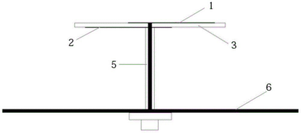
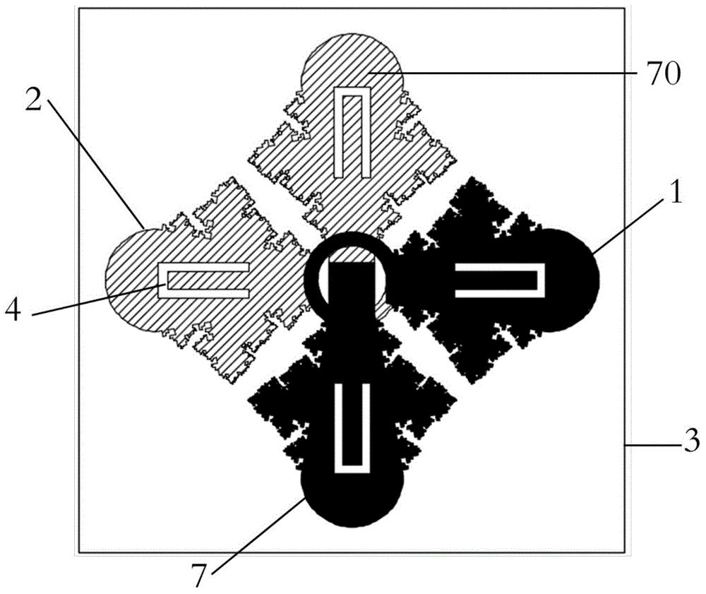
[0041] figure 1 It is a schematic structural diagram of an ultra-wideband fractal antenna in a wireless communication system according to an embodiment of the present invention. Such as figure 1The UWB fractal antenna combined with fractal and defective ground as shown adopts the working principle of crossed oscillators; the UWB antenna consists of a substrate 3, a double-sided radiation unit printed on the surface of the substrate 3, a floor 6 with a fractal defective ground, and a double-sided The radiating unit and the floor 6 consist of half-steel coaxial wires 5 .

[0042] The semi-steel coaxial line 5 is composed of an inner core and a copper skin wrapping the inner core; the substrate 3 and the floor 6 are arranged in a horizontal direction, the semi-steel coaxial line 5 is perpendicular to the base plate 3 and the floor 6, and the semi-steel coaxial line 5 One end is connected with the double-sided radiation unit of the substrate 3 , and the inner core of the other e...


PUM


Abstract

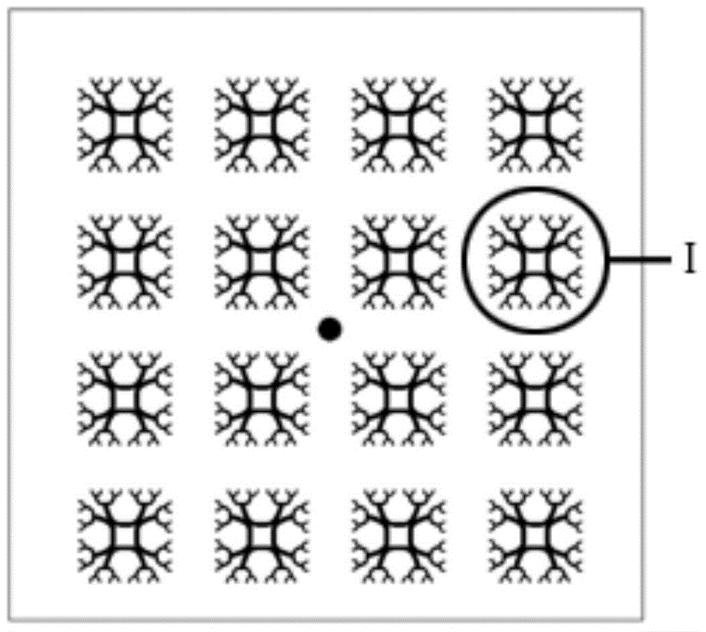
The invention relates to an ultra wide band fractal antenna. The ultra wide band fractal antenna comprises a substrate prepared by an organic magnetic material, a double-face radiation unit printed on a surface of the substrate, a fractal defected ground floor and a semi-steel coaxial wire connecting the double-face radiation unit and the floor, wherein the semi-steel coaxial wire comprises an inner core and a copper sheet wrapping the inner core, the substrate and the floor are respectively horizontally arranged, the semi-steel coaxial wire is perpendicular to the substrate and the floor, one end of the semi-steel coaxial wire is connected with the double-face radiation unit of the substrate, the other end of the semi-steel coaxial wire penetrates through the floor and is connected with an SMA connector, the defected ground floor comprises 4*4 fractal unit slots which are arranged in a mode, and the fractal unit slots are fractal tree annular structures. The ultra wide band fractal antenna has advantages of wide band, high gain, excellent directional diagram, light weight and easy mounting, because of excellent performance, the ultra wide band fractal antenna is an excellent choice for UBW, PCS, WLAN, RFID, WIMAX and other communication systems.

Description

technical field [0001] The invention relates to an antenna device in the communication field, and specifically designs an ultra-wideband fractal antenna. Background technique [0002] The antenna is an essential part of the wireless communication system, which determines whether the wireless communication system can perform its functions and functions normally. However, the traditional antenna has a narrow bandwidth and cannot cover multiple frequency bands at the same time, which cannot meet the needs of modern wireless communication; at the same time, it is also easily affected by the external environment such as rain and fog, and interference from obstacles such as buildings and trees. [0003] Antenna polarization methods include linear polarization and circular polarization. Among them, linearly polarized antennas are widely used in traditional antennas based on the advantages of low cost and simple processing; while linearly polarized waves are easily diffracted and s...

Claims


Application Information

Patent Timeline
Patent Type & Authority Applications(China)
IPC IPC(8): H01Q1/38H01Q1/50H01Q1/48
Inventor 王恩成左申正石璐瑶
Owner NORTH CHINA UNIVERSITY OF TECHNOLOGY
Learn More