Improved vertical type spiral discharge filtering centrifuge

A screw unloading and centrifuge technology, applied to centrifuges, centrifuges with rotating drums, etc., can solve the problems of easy broken solid materials, small diameter of pipe holes, inconvenient installation and use of centrifuges, etc. easily broken effect

Inactive Publication Date: 2016-12-07
莫珉珉 +1
View PDF8 Cites 4 Cited by
  • Summary
  • Abstract
  • Description
  • Claims
  • Application Information

AI Technical Summary

Problems solved by technology

[0002] The prior art vertical screw discharge filter centrifuge, accompanying drawing 2 is the structure of the prior art vertical screw discharge filter centrifuge, one of the disadvantages of this centrifuge: the feed pipe arranged on the top of the centrifuge shell , the diameter of the tube hole is relatively small, which is only suitable for the liquid-solid mixture with good fluidity to flow into the centrifuge for dehydration and separation
For the liquid-solid mixed material with poor fluidity, it is difficult to flow through the feeding pipe of the centrifuge, causing the feeding pipe to be blocked and the centrifuge cannot work normally
The second disadvantage of this prior art vertical screw discharge filter centrifuge is that the liquid-solid mixture enters the centrifuge instantly from the stationary feed pipe, and the helical blades of the high-speed rotating screw conveyor are similar to the high-speed rotation of a pulverizer. The blade can cut solid materials, which are easy to break
The third disadvantage of the vertical screw discharge filter centrifuge in the prior art is that the centrifuge discharges the solids after the dehydration of the liquid-solid mixture into the frame at the bottom of the centrifuge by gravity, and additional conveying equipment is required to remove the solids. The centrifuge should be transported out of the machine, or the installation height of the centrifuge should be raised so that the solid matter can be discharged out of the machine. It is inconvenient to install and use the centrifuge.

Method used


Image

  • Improved vertical type spiral discharge filtering centrifuge
  • Improved vertical type spiral discharge filtering centrifuge

Examples


Embodiment Construction

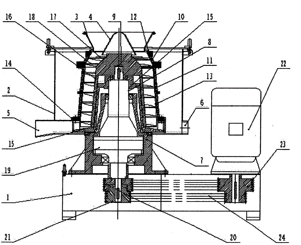
[0018] Below in conjunction with the embodiment shown in the accompanying drawings, the scheme of the present invention is described in detail as follows:

[0019] as attached figure 1 As shown, an improved vertical screw discharge filter centrifuge of the present invention, the frame 1 is fixed with a bearing seat 7 and a motor 22 is fixed. The flange at the upper end of the bearing housing 7 is connected with the housing 2 . Described drum transmission shaft 8 and coaxial line described screw conveyor transmission shaft 9 are installed in described bearing block 7, and two axles can rotate relatively. The lower end of the drum drive shaft 8 is connected with the casing of the differential 19, the drum drive shaft 8 is connected with the drum fixing flange 15, and the upper cone of the rotary drum is The drum 10 and the lower conical or cylindrical drum 11 are connected with the drum fixing flange 15, and the lower end of the screw conveyor transmission shaft 9 is connected...


PUM


Abstract

The invention discloses an improved vertical type spiral discharge filtering centrifuge. The improved vertical type spiral discharge filtering centrifuge comprises a centrifuge base, a shell, an inner guide conical barrel, an outer guide conical barrel, an upper drum, a lower drum, an upper drum filter screen, a lower drum filter screen, a spiral conveyor, a material accelerating disc, a spiral blade, a differential mechanism and the like. A poor-liquidity or solid breakable solid-liquid mixture enters the material accelerating disc from the inner guide conical barrel and the outer guide conical barrel and enters a centrifugal dehydration cavity after acceleration. Materials are not liable to be blocked and not liable to be broken by the spiral blade. In order to prevent the materials from spattering and overflowing from the top of the upper drum, the material accelerating disc shall be a distance lower than the top end of the upper drum. In order to prevent the materials being attaching to the upper drum filter screen in a self-locking mode, the half cone angle of the inner wall of the upper drum shall be larger than the frictional angle of the materials and the upper drum filter screen. After the materials enter the centrifuge, liquid is discharged from the drums and liquid discharge holes of the filter screens through centrifugal force, solids are pushed into solid discharge holes of the drums by the spiral blade through rotation speed difference generated by the differential mechanism and discharged from a solid discharge pipe on the side lower portion of the shell through centrifugal force, and automatic and continuous dehydration separation is achieved.

Description

technical field [0001] The invention relates to a vertical screw discharge filter centrifuge, in particular to an improved vertical screw discharge filter centrifuge suitable for continuous automatic dehydration and separation of liquid-solid mixture materials with poor fluidity or easily broken solid materials. Background technique [0002] The prior art vertical screw discharge filter centrifuge, accompanying drawing 2 is the structure of the prior art vertical screw discharge filter centrifuge, one of the disadvantages of this centrifuge: the feed pipe arranged on the top of the centrifuge shell , The diameter of the tube hole is relatively small, which is only suitable for the liquid-solid mixture with good fluidity to flow into the centrifuge for dehydration and separation. For the liquid-solid mixed material with poor fluidity, it is difficult to flow through the feeding pipe of the centrifuge, causing the feeding pipe to be blocked and the centrifuge cannot work norma...

Claims


Application Information

Patent Timeline
Patent Type & Authority Applications(China)
IPC IPC(8): B04B1/20B04B11/02B04B15/00
Inventor 吴培钧莫珉珉
Owner 莫珉珉
Why Eureka
Try Eureka