A kind of internal rotation feeding device used for large-scale thin-walled cylindrical piece counter-wheel spinning equipment

A technology of spinning equipment and feeding device, which is applied in the field of feeding device, can solve the problems of long manufacturing cycle, high mold cost, and large force on the screw, and achieve the advantages of reduced manufacturing cycle, good versatility, and reduced production cost Effect

Active Publication Date: 2018-09-07
HARBIN INST OF TECH
View PDF5 Cites 0 Cited by
  • Summary
  • Abstract
  • Description
  • Claims
  • Application Information

AI Technical Summary

Problems solved by technology

[0003] The purpose of the present invention is to solve the problems of high mold cost, poor versatility, long manufacturing cycle and large force on the screw in the existing molded spinning equipment

Method used


Image

  • A kind of internal rotation feeding device used for large-scale thin-walled cylindrical piece counter-wheel spinning equipment
  • A kind of internal rotation feeding device used for large-scale thin-walled cylindrical piece counter-wheel spinning equipment
  • A kind of internal rotation feeding device used for large-scale thin-walled cylindrical piece counter-wheel spinning equipment

Examples


specific Embodiment approach 1

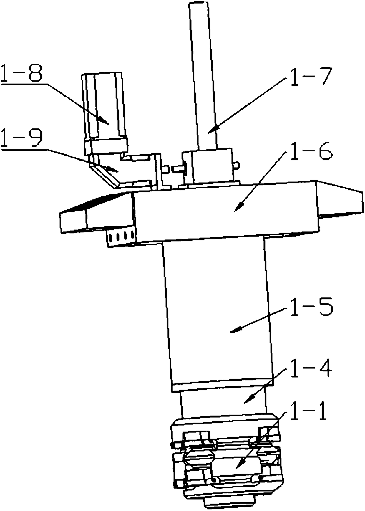
[0015] Specific embodiment one: combine 1 to Figure 6 This embodiment is described. An internal rotation feed device for large thin-walled cylindrical part counter-wheel spinning equipment in this embodiment includes a wheel seat guide sleeve 1-1, a wedge guide sleeve 1-4, a transition sleeve Cylinder 1-5, upper beam 1-6, feed screw 1-7, inner rotation motor 1-8, reducer 1-9, tapered wedge 2-2, multiple inner rotation wheel seats 2-3, A plurality of inner rollers 2-4 and a plurality of roller shafts 3-2,

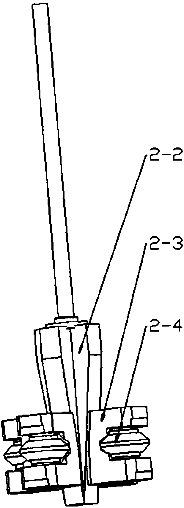
[0016] The tapered wedge 2-2 is set on the feed screw 1-7, and a plurality of inner spiral wheel seats 2-3 are evenly distributed in a ring on the tapered wedge 2-2, and each inner spiral wheel seat 2-3 A rotary wheel shaft 3-2 is installed in the vertical rotation, and an internal rotary wheel 2-4 is installed on each rotary wheel shaft 3-2. There are cross chute, the cross chute of the wedge guide sleeve 1-4 and the guide sleeve 1-1 of the wheel seat are aligned with ea...

specific Embodiment approach 2

[0018] Specific implementation mode two: combination figure 2 To illustrate this embodiment, the inner roller seat 2-3 of this embodiment has a U-shaped structure, and the upper and lower ends of the inner roller and the tapered roller bearings set on the front and rear sections of the roller shaft form an interference fit. Such an arrangement facilitates the provision of a spinning working environment and space for the rotary wheel. Other compositions and connections are the same as in the first embodiment.

specific Embodiment approach 3

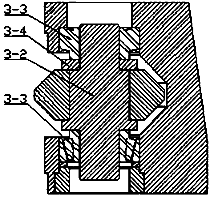
[0019] Specific implementation mode three: combination image 3 To illustrate this embodiment, the wheel shaft 3 - 2 of this embodiment is a four-stage stepped shaft, including a three-stage stepped shaft whose diameter gradually increases from top to bottom. In this way, the diameter of the assembly section of the inner hole of the roller is greater than that of the head and tail sections; the inner diameter of the roller bearing spacer is the same as the diameter of the first and last ends of the roller shaft, and is installed on the spinning shaft to separate the roller and the tapered roller bearing. Other compositions and connections are the same as those in Embodiment 1 or Embodiment 2.


PUM


Abstract

The invention discloses an internal rotation feeding device for large thin-wall cylindrical part pair wheel spinning equipment, relates to an internal rotation feeding device, and aims to solve the problems of high mold cost, weak generality and long manufacturing period in traditional mold spinning equipment. A conical wedge block coats a feeding lead screw; multiple internal rotation wheel bases are annularly and uniformly mounted on the conical wedge block; one rotating shaft is vertically and rotationally mounted in each internal rotation wheel base; one internal rotation wheel is mounted on each rotating shaft; cross chutes are respectively formed in a rotating base guide sleeve and a wedge block guide sleeve, and are mutually aligned and buckled up and down; a transition sleeve coats the feeding lead screw, and is positioned at the upper end of the wedge block guide sleeve; an upper cross beam is mounted on the transition sleeve; an internal rotation motor is mounted on a speed reducer for transferring power to a speed reducer; and the speed reducer drives the feeding lead screw to rotate. The internal rotation feeding device is suitable for the thin-wall cylindrical part pair wheel spinning equipment.

Description

technical field [0001] The invention relates to a feeding device, in particular to an inner-rotating feeding device for wheel-to-wheel spinning equipment for large thin-walled cylindrical parts. Background technique [0002] Wheel spinning is the best process for forming large-diameter cylindrical parts. Through the transformation of the spinning machine and the design of the spinning tooling, the process parameters such as the blank, the spinning wheel, the spindle speed, the feed ratio and the number of the wheel pairs have a great influence on the forming, especially in the initial wall thickness. In the case of the same degree of deformation, compared with core mold spinning, the deformation of the counter wheel spinning is completed by the inner and outer symmetrical wheel pairs, and the spinning force is reduced by half; due to the symmetrical material flow, the deformation of the inner and outer layers of the billet is equivalent, making Counter wheel spinning produc...

Claims


Application Information

Patent Timeline
Patent Type & Authority Patents(China)
IPC IPC(8): B21D22/14
CPCB21D22/14
Inventor 徐文臣王森鹏单德彬陈宇靳学泽杨川
Owner HARBIN INST OF TECH
Why Eureka
Try Eureka