
Pipe cutting device

A cutting device and pipe fitting technology, applied in the field of cutting, can solve the problems of affecting the forming rate of copper pipes, the waste of copper pipe material, and easy loss, etc., and achieve the effects of reducing material loss, improving utilization rate, and improving forming rate

Active Publication Date: 2016-12-07
易捷通电子有限公司
View PDF7 Cites 5 Cited by
  • Summary
  • Abstract
  • Description
  • Claims
  • Application Information

AI Technical Summary

Problems solved by technology

[0003] When cutting the existing copper pipes, it is mainly to directly cut the hollow copper pipes. You only need to move the copper pipes to the cutting position, and then you can use the sawtooth to cut the copper pipes. When cutting, because the copper pipes are hollow, so It is easy to produce a large amount of deformation, which affects the forming rate of the copper tube; and the saw teeth are prone to loss during the sawing process, resulting in waste of copper tube material

Method used


Image

  • Pipe cutting device
  • Pipe cutting device
  • Pipe cutting device

Examples


Embodiment Construction

[0026] The following will clearly and completely describe the technical solutions in the embodiments of the present invention with reference to the accompanying drawings in the embodiments of the present invention. Obviously, the described embodiments are only some, not all, embodiments of the present invention. Based on the embodiments of the present invention, all other embodiments obtained by persons of ordinary skill in the art without making creative efforts belong to the protection scope of the present invention.

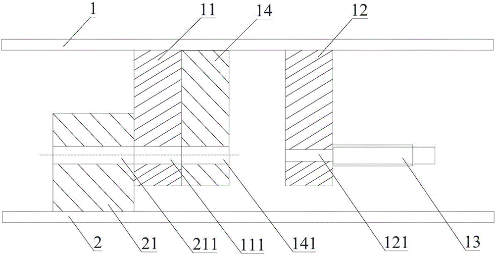
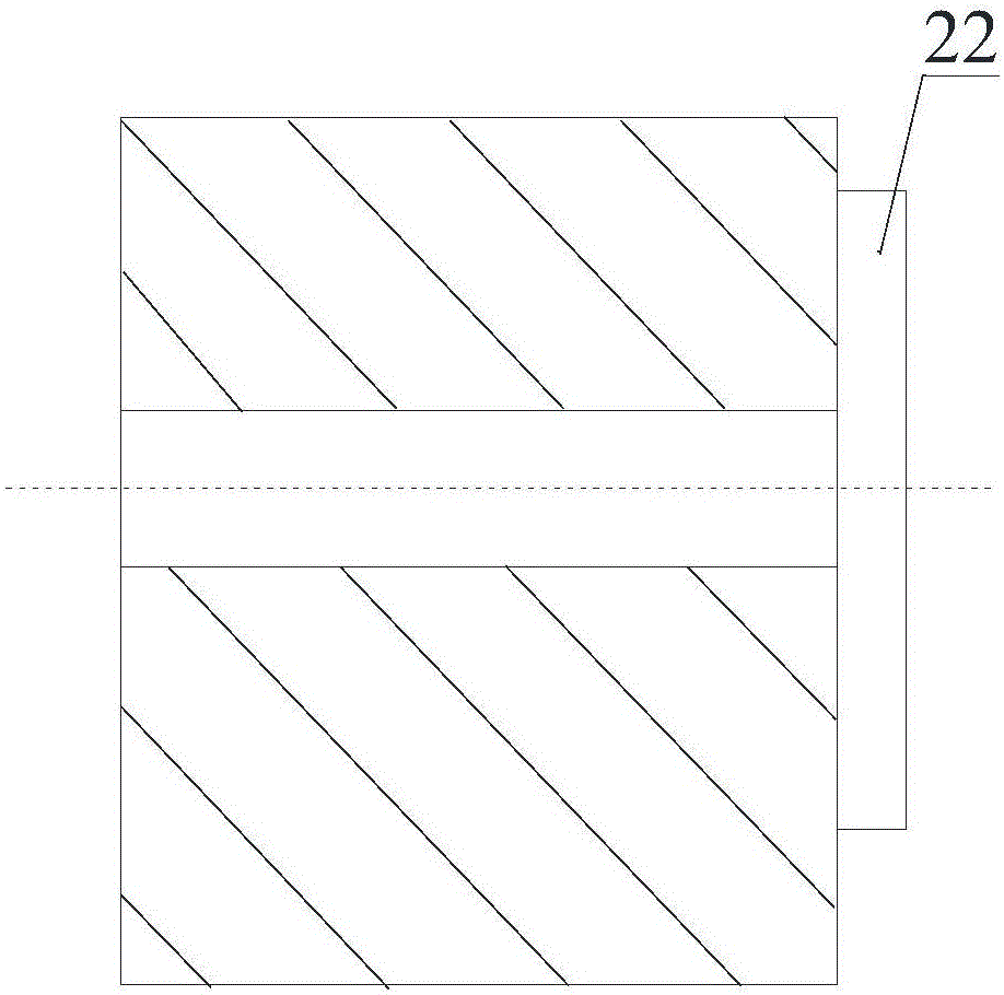
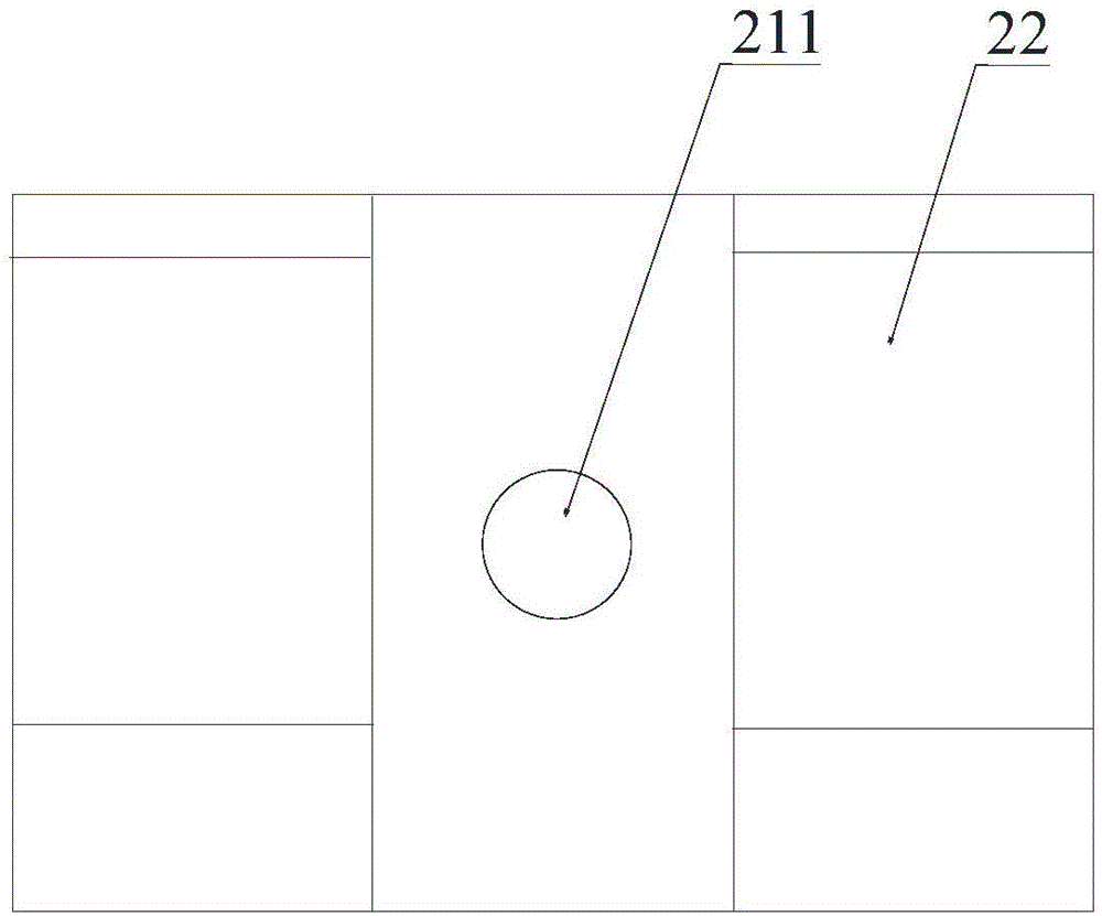
[0027] See Figure 1 to Figure 3 , the pipe cutting device provided by the embodiment of the present invention includes an upper processing seat 1 and a lower processing seat 2 . Wherein: the lower processing seat 2 is provided with a cutting module 21, the cutting module 21 is provided with a first through hole 211, the upper processing seat 1 is provided with a punch 11 that fits with the cutting module 21, the punch 11 is A second through hole 111 is provi...


PUM


Abstract

The invention discloses a pipe cutting device. The pipe cutting device comprises an upper machining base and a lower machining base, wherein the lower machining base is provided with a cutting module with a first through hole, a first inner support pipe with magnetism, and a magnetic body for adjusting axial position of the first inner support pipe; the upper machining base is provided with a punch bonded with the cutting module and provided with a second through hole, and an elastic ejector rod for pushing a second inner support pipe; and during cutting, the first inner support pipe and the second inner support pipe are respectively positioned on two sides of a cutting port. During cutting by the pipe cutting device, as the inner support pipes are arranged in a pipe, and the two inner support pipes are respectively positioned on two sides of the cutting port, when the punch downwards moves to cut off the pipe, the deformation of the cutting port of the pipe is lower, and the yield of the pipe is improved; and when the punch is acted on the pipe, the pipe is cut off mainly through shearing force, so that the pipe material wear and loss can be reduced, and the pipe material utilization rate is increased.

Description

technical field [0001] The invention relates to the technical field of cutting, and more specifically, relates to a pipe cutting device. Background technique [0002] Copper tubes are widely used in many fields, especially in secondary wiring. When producing copper tubes, cutting the copper tubes is a very important and necessary step. After the cutting operation, the copper tubes whose length meets the production requirements can be obtained. [0003] When cutting the existing copper pipes, it is mainly to directly cut the hollow copper pipes. You only need to move the copper pipes to the cutting position, and then you can use the sawtooth to cut the copper pipes. When cutting, because the copper pipes are hollow, so It is easy to produce a large amount of deformation, which affects the forming rate of the copper pipe; and the saw teeth are prone to loss during the sawing process, resulting in waste of copper pipe material. [0004] To sum up, how to provide a pipe fittin...

Claims


Application Information

Patent Timeline
Patent Type & Authority Applications(China)
IPC IPC(8): B21D28/02
CPCB21D28/02
Inventor 叶展宇
Owner 易捷通电子有限公司
Learn More