Punching device

A technology of punching device and punch, which is applied in the field of punching device and motor shell punching, can solve the problems of low punching efficiency, low positioning efficiency, poor punching quality, etc., and achieve good punching quality, Reduce labor intensity and high punching efficiency

Inactive Publication Date: 2016-12-07
苏州任翔金属制品有限公司
View PDF5 Cites 3 Cited by
  • Summary
  • Abstract
  • Description
  • Claims
  • Application Information

AI Technical Summary

Problems solved by technology

However, in the prior art, due to the cylindrical structure of the motor housing, punching holes are made on its outer peripheral surface, the positioning quality of the product is poor, and the positioning efficiency is low, resulting in low punching efficiency. Punching, poor positioning quality, resulting in poor punching quality and low pass rate of products

Method used


Image

  • Punching device
  • Punching device
  • Punching device

Examples


Embodiment 1

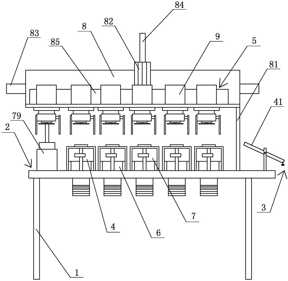
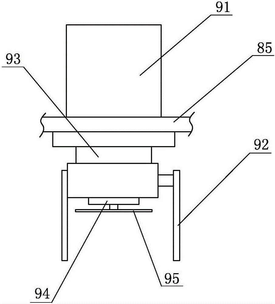
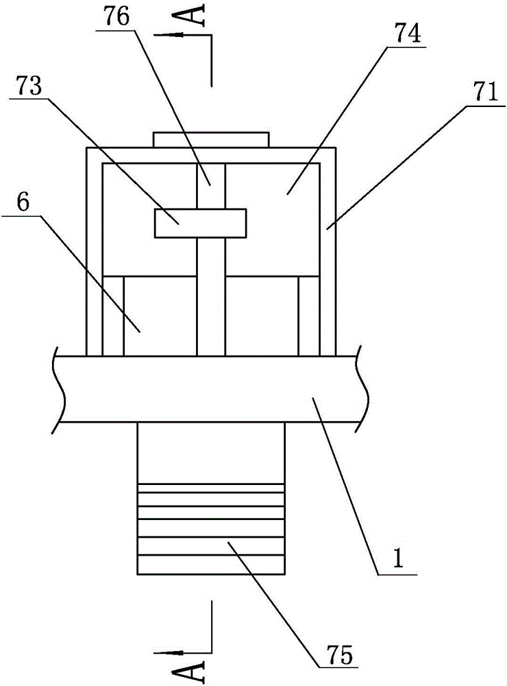
[0026] Embodiment one: see Figure 1~5 As shown, a punching device includes a frame 1, one end of the frame 1 is provided with a feed end 2, and the other end is provided with a discharge end 3, the gap between the feed end 2 and the discharge end 3 The frame 1 is provided with 5 groups of punching devices 4 and a product grasping device 5 arranged above the punching device 4, and 5 groups of punching devices 4 are arranged on the frame 1 at intervals from left to right. The punching device 4 includes a product positioning seat 6 and a punching mechanism 7 arranged on both sides of the product positioning seat 6, and the product grabbing device 5 includes a moving mechanism 8 and a plurality of groups of grasping mechanisms 9 arranged on the moving mechanism 8, The distance between adjacent grabbing mechanisms 9 is equal to the spacing between adjacent product positioning seats 6 , and the grabbing mechanisms 9 are arranged above the product positioning seats 6 .

[0027] In ...


PUM


Abstract

The invention discloses a punching device. The punching device is characterized by comprising a rack; one end of the rack is provided with a feeding end, and the other end of the rack is provided with a discharging end; a plurality of sets of punching device bodies and a product grabbing device are arranged in the positions, between the feeding end and the discharging end, of the rack; the multiple sets of punching device bodies are arranged on the rack at intervals from left to right; each punching device body comprises a product positioning base and punching mechanisms arranged on the two sides of the product positioning base; the product grabbing device comprises a moving mechanism and a plurality of sets of material grabbing mechanisms arranged on the moving mechanism; the distance between the adjacent material grabbing mechanisms is equal to the distance between the adjacent product positioning bases; and the material grabbing mechanisms are arranged above the product positioning bases. According to the punching device, the punching efficiency and the punching quality of products are improved, and the qualified rate of the products is increased.

Description

technical field [0001] The invention relates to a punching device, in particular to a punching device, which is mainly used for punching hollow cylindrical metal structures, especially for punching motor casings. Background technique [0002] A motor, commonly known as a motor, refers to an electromagnetic device that converts or transmits electrical energy according to the law of electromagnetic induction. In the circuit, it is represented by the letter M (the old standard is D). Its main function is to generate driving torque as a power source for electrical appliances or various machinery. The generator is represented by the letter G in the circuit. Its main function is to convert electrical energy into mechanical energy. [0003] Wherein, the housing of the motor is provided with a plurality of through holes, and a stamping device is generally used to punch the housing of the motor. However, in the prior art, due to the cylindrical structure of the motor housing, pun...

Claims


Application Information

Patent Timeline
Patent Type & Authority Applications(China)
IPC IPC(8): B21D28/34B21D43/10B21D45/04
CPCB21D28/34B21D43/027B21D43/105B21D45/003
Inventor 杨红云
Owner 苏州任翔金属制品有限公司
Why Eureka
Try Eureka