
Knife grinder device for cutting machine

A technology for sharpening a grinding wheel and a cutting machine, which is applied in the field of cutting machines, can solve problems such as inconvenient disassembly and assembly, and achieve the effects of convenient disassembly and assembly, good effect and convenient manufacturing.

Active Publication Date: 2016-12-07
BULLMER ELECTROMECHANICAL TECH
View PDF8 Cites 1 Cited by
  • Summary
  • Abstract
  • Description
  • Claims
  • Application Information

AI Technical Summary

Problems solved by technology

It is more inconvenient to disassemble

Method used


Image

  • Knife grinder device for cutting machine
  • Knife grinder device for cutting machine

Examples


Embodiment Construction

[0035] The following are specific embodiments of the present invention and in conjunction with the accompanying drawings, the technical solutions of the present invention are further described, but the present invention is not limited to these embodiments.

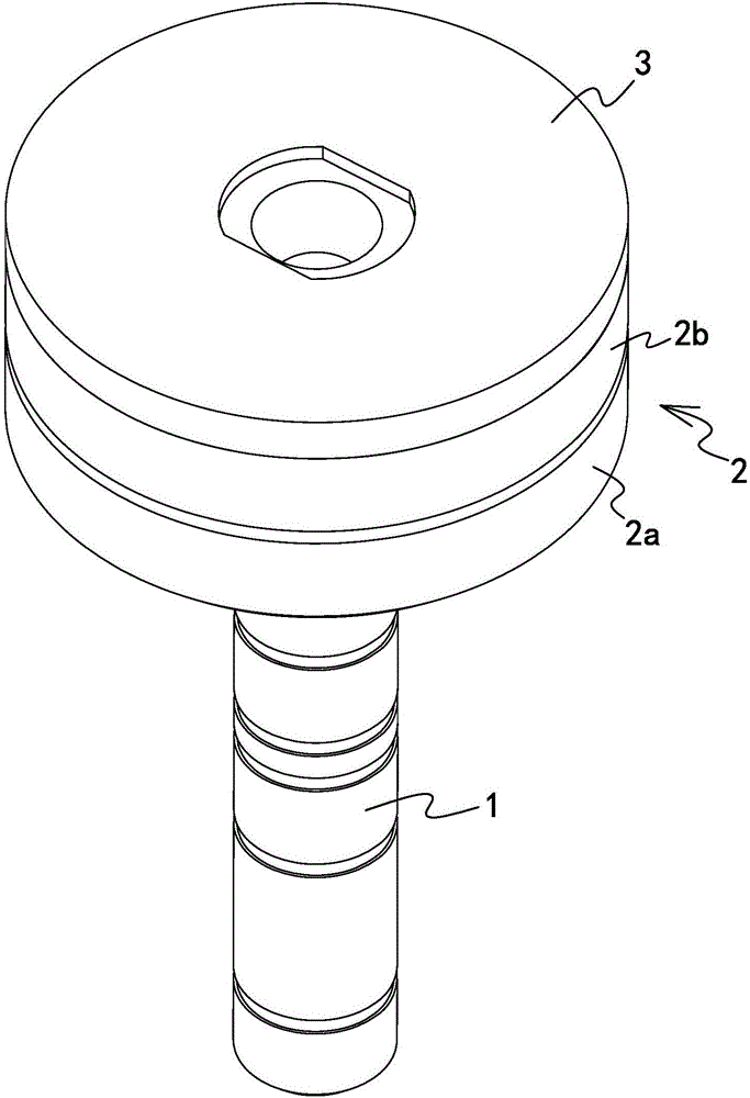
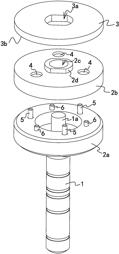
[0036] like figure 1 and figure 2 As shown, the grinding wheel device for cutting machines includes a rotating shaft 1 , a base 2 fixed at one end of the rotating shaft 1 and a grinding wheel 3 arranged on the base 2 .

[0037] Base 2 comprises fixed seat one 2a and fixed seat two 2b, fixed seat one 2a is fixed on the rotating shaft 1, fixed seat two 2b is fixed on the fixed seat one 2a by bolt one 5, and emery wheel 3 is arranged on the fixed seat two 2b. Specifically, the first fixing base 2a has a through hole, the second fixing base 2b has a threaded hole one corresponding to the position of the through hole, and the bolt one 5 is threaded through the through hole and fixed on the first threaded hole.

[0038] The s...


PUM


Abstract

The invention discloses a knife grinder device for a cutting machine and the cutting machine, and solves the problem of inconvenience for dismounting of a grinding wheel in a traditional grinding wheel device. The knife grinder device for the cutting machine comprises a rotating shaft, a base fixed at one end of the rotating shaft, and a grinding wheel arranged on the base; the grinding wheel is peripherally fixed with the base; and the grinding wheel is axially fixed on the base through a magnet. In the device, as the grinding wheel is fixed on the base through the magnet, the grinding wheel is more convenient for dismounting.

Description

technical field [0001] The invention belongs to the technical field of cutting machines, and relates to a knife grinding wheel device for cutting machines. Background technique [0002] Chinese utility model patent (authorized announcement number: CN202062268U, authorized announcement date: 20111207) discloses a sharpening device for high-rise automatic cutting machines. Two motors are arranged on one side of the sharpening motor mounting plate, and the sharpening motor is installed On the other side of the board, there are two sharpening wheels respectively connected to the motor. On the sharpening motor mounting plate under the motor, there is an adjustment block that can adjust whether the two motors are on the same line. The cylinder is installed on the cylinder bracket. , the cylinder bracket is fixedly connected with the sharpening motor mounting plate through the connection block, the cylinder piston is connected with the connection block, a dial sleeve is arranged on...

Claims


Application Information

Patent Timeline
Patent Type & Authority Applications(China)
IPC IPC(8): B24B3/36B24B41/047
CPCB24B3/36B24B41/047
Inventor 娄正宇姚金领
Owner BULLMER ELECTROMECHANICAL TECH
Learn More