Transfer vehicle for plastic machine enclosures

A plastic casing and transfer car technology, applied in the transfer car field, can solve the problems of easy loss, laborious manual handling, poor working environment, etc., and achieve the effects of convenient use and recording, beautifying the working environment and improving the service life

Inactive Publication Date: 2016-12-07
TIANJIN LIANJIE PLASTIC PROD
View PDF0 Cites 0 Cited by
  • Summary
  • Abstract
  • Description
  • Claims
  • Application Information

AI Technical Summary

Problems solved by technology

[0002] In the production of injection molding industry, workpieces often need to be transferred from one place to another for inspection or processing. Due to the large number, large volume, and laborious manual handling of injection-molded plastic casings
In the processing and production work, the labor protection supplies and record books needed by the staff have nowhere to place and are easy to lose. At the same time, during the loading process, the product may be damaged due to the impact force during the contact process, which reduces the qualified rate of the product.
In addition, during the injection molding production process, waste is easily generated, and the working environment is poor. The waste scattered on the ground during the transfer process will hinder the operation of the transfer vehicle

Method used


Image

  • Transfer vehicle for plastic machine enclosures
  • Transfer vehicle for plastic machine enclosures

Examples


Embodiment 1

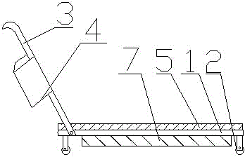
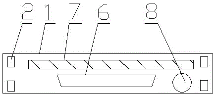
[0011] The invention provides a transfer vehicle with a plastic casing, which includes a base 1, universal wheels 2, a push armrest 3, an accessory box 4, a buffer layer 5, a dust collection box 6, a vacuum cleaner 7, and a power supply device 8, and a vacuum cleaner is installed under the base 1 7. A power supply device 8 and a dust collection box 6 are respectively installed on the rear of the vacuum cleaner 7. One end of the vacuum cleaner 7 is connected to the power supply device 8, and the other end is connected to the dust collection box 6. Universal wheels 2 are installed on the four corners of the bottom of the base 1. One side of the base 1 is connected with the push armrest 3, the accessory box 4 is fixed on the push armrest 3, and the buffer layer 5 is installed above the base 1.

Embodiment 2

[0013] During use, push the present invention to the specified position by pushing the armrest 3, take out the labor protection article from the accessories box 4, put the processed workpiece on the base 1, and because the buffer layer 5 is installed on the base 1, the workpiece and the base 1 can be effectively reduced. The impact force generated by the contact not only improves the service life of the base 1, but also protects the workpiece, avoids damage to the workpiece caused by bumping, records data after loading, and puts the record book in the accessory box 4, and pushes the invention by pushing the armrest 3, During the running process, the power supply device 8 can be turned on, and the vacuum cleaner 7 works. During the running process, the dust and processing waste are absorbed and collected in the dust collecting box 6, which can be dumped regularly. The invention is simple in structure and easy to operate, not only can facilitate workers to carry the workpiece, bu...


PUM


Abstract

The invention discloses a transfer vehicle for plastic machine enclosures. The transfer vehicle comprises a base, universal wheels and a pushing handrail. The transfer vehicle is characterized by further comprising a fitting box, a buffer layer and the like, wherein a dust collector is mounted below the base; a power supply device and a dust collecting box are separately mounted behind the dust collector; one end of the dust collector is connected to the power supply device; the other end of the dust collector is connected to the dust collecting box; universal wheels are mounted on four corners of the bottom of the base; one side of the base is connected to the pushing handrail; and the fitting box is fixedly arranged on the pushing handrail. According to the transfer vehicle disclosed by the invention, the buffer layer is mounted on the base, so that the service life of the transfer vehicle is prolonged; the fitting box is fixedly arranged on the pushing handrail, so that a worker conveniently operates and records. The transfer vehicle is simple in structure, and is convenient to operate and the worker transports workpieces conveniently; moreover, the service life of the transfer vehicle can be prolonged, workpieces are prevented from being damaged due to bumping; and meanwhile, dust particles in air further can be absorbed, a working place is cleaned, and a working environment is beautified.

Description

technical field [0001] The invention relates to a transfer cart, in particular to a transfer cart with a plastic casing. Background technique [0002] In the production of injection molding industry, workpieces often need to be transferred from one place to another for inspection or processing. Due to the large number and large volume of injection molded plastic casings, manual handling is laborious. In the processing and production work, the labor protection supplies and record books needed by the staff have nowhere to place and are easy to lose. At the same time, the product may be damaged due to the impact force during the loading process, which reduces the qualified rate of the product. In addition, during the injection molding process, waste is easily generated, and the working environment is poor. The waste scattered on the ground during the transfer process will hinder the operation of the transfer vehicle. Contents of the invention [0003] According to the above ...

Claims


Application Information

Patent Timeline
Patent Type & Authority Applications(China)
IPC IPC(8): B29C31/00
Inventor 杜庆来
Owner TIANJIN LIANJIE PLASTIC PROD
Why Eureka
Try Eureka