
Mold temperature control device

A mold temperature control and heating device technology, applied in the field of mold forming, can solve the problems of energy consumption and production cost increase, lower product surface quality, large residual stress, etc., to reduce production efficiency, overcome inherent defects, and shorten molding cycle Effect

Inactive Publication Date: 2016-12-07
苏州路熙光电科技有限公司
View PDF2 Cites 1 Cited by
  • Summary
  • Abstract
  • Description
  • Claims
  • Application Information

AI Technical Summary

Problems solved by technology

During the molding process, the low mold temperature will lead to the cooling of the polymer melt during the flow of the die. Due to the early cooling, a condensation layer will be formed on the wall of the cavity, which will hinder the molding of the melt and reduce the filling of the melt. mold ability and transfer ability
Therefore, traditional injection molding technology is difficult to apply to optical products with high transparency, plastic parts with microstructure on the surface, composite products with high strength, and ultra-long thin-walled parts or large covering parts with high flow length.
In addition, premature cooling of the polymer melt will also cause surface defects such as weld marks, flow marks, and depressions on the surface of plastic parts, thereby greatly reducing the surface quality of the product. It not only increases the production cost and energy consumption, but also pollutes the environment and adversely affects the health of operators.
From the above analysis, it can be seen that the traditional injection molding technology has been difficult to meet the development needs of the injection molding industry, and the market urgently needs new molding technology to solve the above molding problems
In recent years, the emergence of new injection molding technologies such as gas-assisted and water-assisted has improved the filling capacity of the melt to a certain extent, making it possible to form plastic products with a large flow-to-length ratio, but they have not fundamentally changed the polymer melt. Therefore, the residual stress of molded products using this technology is relatively large. At the same time, excessive injection pressure and holding pressure will also lead to an increase in energy consumption and production costs, and the surface defects of the product still cannot be completely solved.

Method used


Image

  • Mold temperature control device
  • Mold temperature control device
  • Mold temperature control device

Examples


Embodiment Construction

[0017] The implementation of the present invention will be illustrated by specific specific examples below, and those skilled in the art can easily understand other advantages and effects of the present invention from the contents disclosed in this specification.

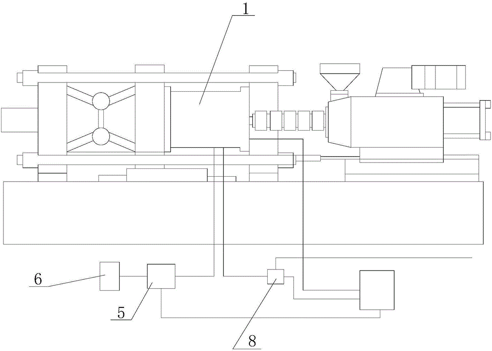
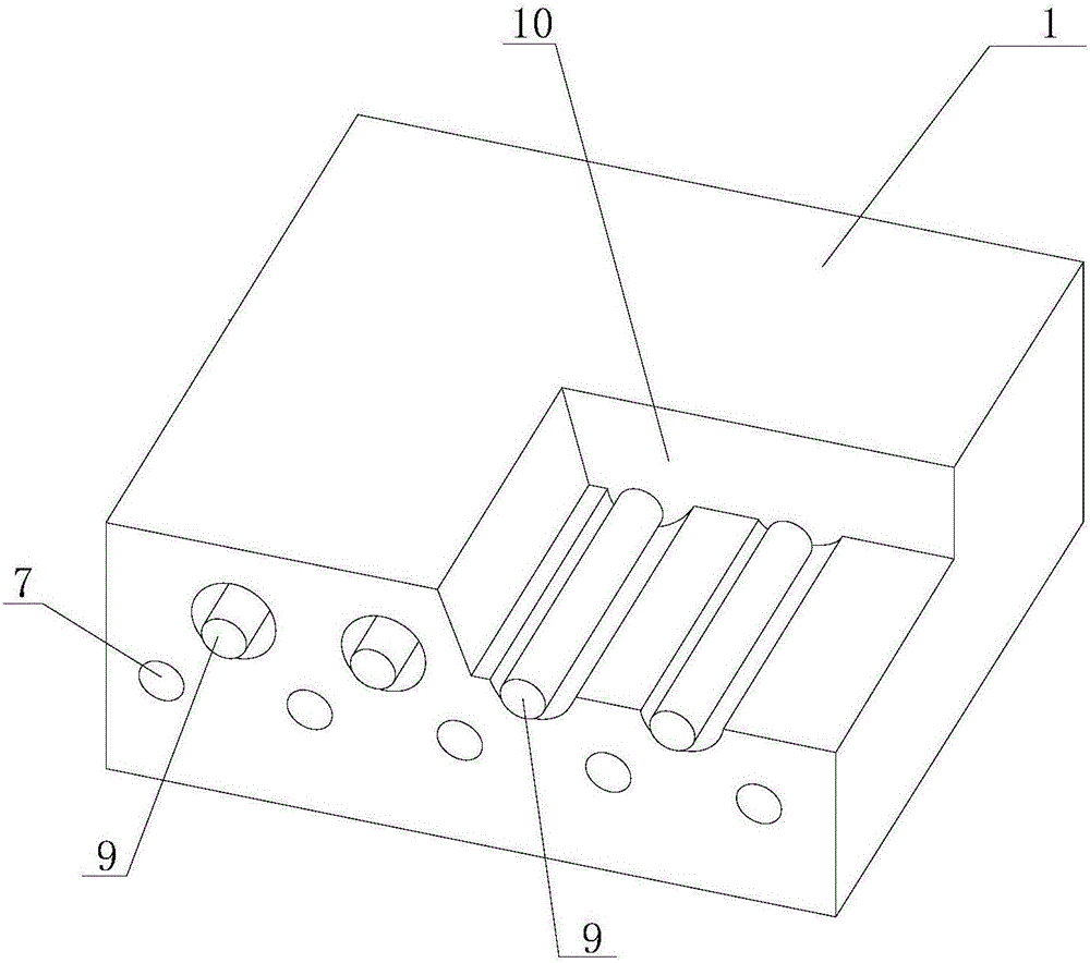
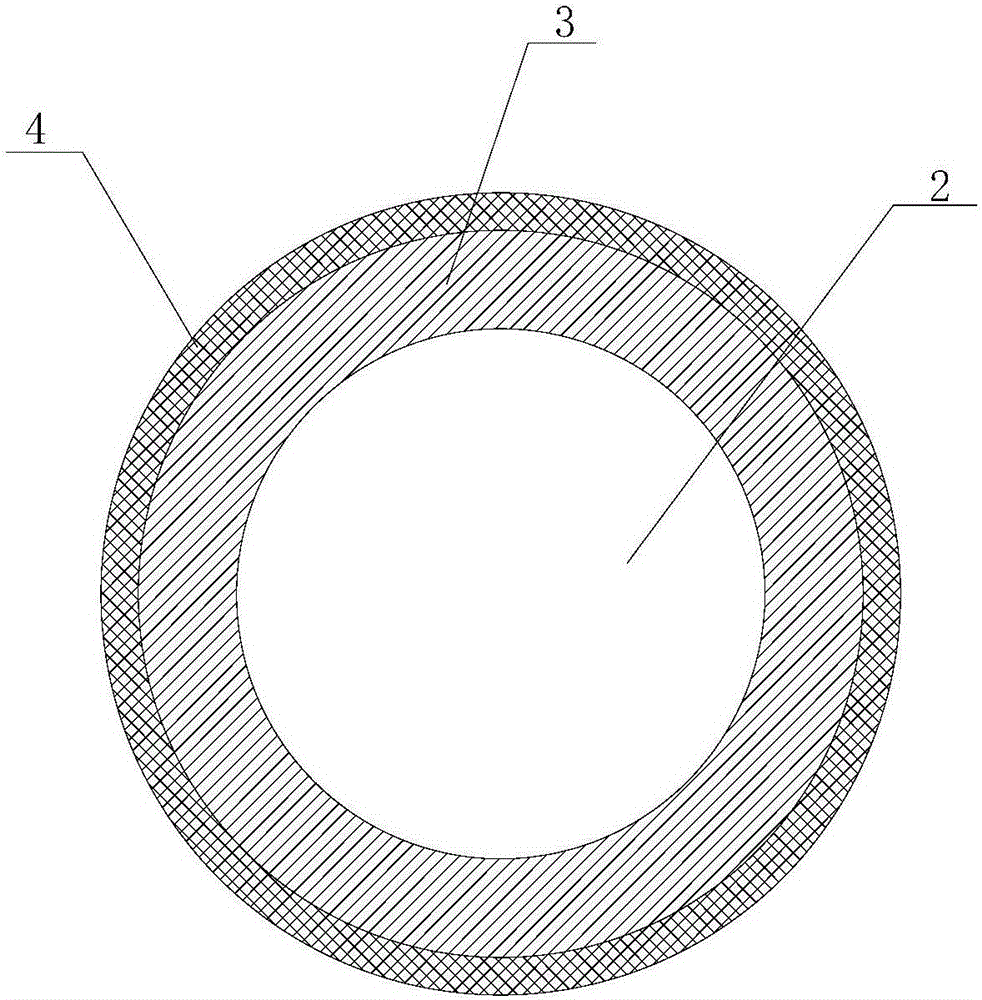
[0018] see Figure 1 to Figure 4 . It should be noted that the structures, proportions, sizes, etc. shown in the drawings attached to this specification are only used to match the content disclosed in the specification, for those who are familiar with this technology to understand and read, and are not used to limit the implementation of the present invention. Limiting conditions, so there is no technical substantive meaning, any modification of structure, change of proportional relationship or adjustment of size, without affecting the effect and purpose of the present invention, should still fall within the scope of the present invention. The disclosed technical content must be within the scope covered. At the sa...


PUM


Abstract

The invention discloses a mold temperature control device which comprises a mold, a cooling system and heating devices. A shell of the mold is provided with cooling pipelines. A cooling water outlet of the cooling system communicates with water inlets of the cooling pipelines through pipelines. Each heating device comprises a ceramic core bar, a coil and an insulating layer, wherein the coil is wound around the ceramic core bar, the coil is wrapped by the insulating layer, the heating device is inserted in a cavity of the mold. By the adoption of a variable-mold-temperature injection molding method, a dynamic mold temperature control strategy is adopted, in other words, the mold is rapidly heated before glue injection, high-mold-temperature injection is achieved, then the forming period is shortened through fast cooling, and therefore inherent defects of a traditional injection molding technology are overcome while the production efficiency is not reduced.

Description

technical field [0001] The invention belongs to the field of mold forming, and in particular relates to a mold temperature control device. Background technique [0002] With the development of home appliances, communications, consumer electronics, automotive interiors, optoelectronics and other industries, consumers have put forward requirements for plastic products in terms of thinner wall thickness, more complex structure, more beautiful surface, and higher strength. For traditional injection molding technology, a constant temperature mold temperature control strategy is adopted. Due to the limitation of the molding cycle, the mold temperature is relatively low (generally less than 80°C). During the molding process, the low mold temperature will lead to the cooling of the polymer melt during the flow of the die. Due to the early cooling, a condensation layer will be formed on the wall of the cavity, which will hinder the molding of the melt and reduce the filling of the me...

Claims


Application Information

Patent Timeline
IPC IPC(8): B29C45/73B29C45/78
CPCB29C45/73B29C45/78B29C2945/76531
Inventor 张贻青俞伟兵
Owner 苏州路熙光电科技有限公司
Learn More