Voltage-drop compensation method for power output lines and switch power supply

A technology of power output and switching power supply, which is applied in the fields of digital electronics, automatic control, analog electronics, and power electronics. defects, the effect of improving the load regulation rate

Active Publication Date: 2010-06-16
KYLAND TECH CO LTD
View PDF0 Cites 12 Cited by
  • Summary
  • Abstract
  • Description
  • Claims
  • Application Information

AI Technical Summary

Problems solved by technology

[0010] Method 2 reduces the resistance on the output line of the output power supply, which is effective in improving the load regulation rate, but the improvement effect is not clear, and the loss on the output line of the power supply is still not compensated
[0011] The adjustment rate of the third option will be significantly improved, but it needs an additional power output line, and it needs special treatment for the power output line, which is not convenient to use.
[0012] In addition, once the remote transmission line has an open circuit fault, the voltage feedback loop will be disconnected, the output voltage cannot be controlled, and the load equipment will be damaged

Method used


Image

  • Voltage-drop compensation method for power output lines and switch power supply
  • Voltage-drop compensation method for power output lines and switch power supply
  • Voltage-drop compensation method for power output lines and switch power supply

Examples


Embodiment Construction

[0021] The present invention will be further described below in conjunction with the accompanying drawings.

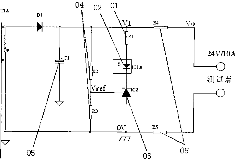
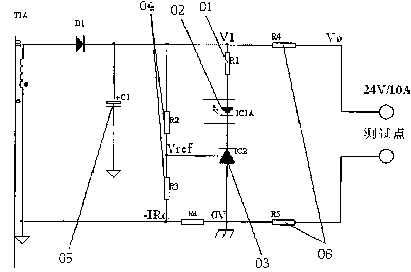
[0022] figure 1 Indicates the circuit diagram of the feedback part of the traditional switching power supply; sampling resistor 04: determines the output voltage; reference source 03: generates the reference voltage; photocoupler 02: transmits the secondary feedback signal to the primary side; wire resistance 06: feedback in the actual power supply The real impedance existing in a section of wire from the sampling point to the load end; current limiting resistor 01: limit the current in the optocoupler, and set the operating point of the feedback loop.

[0023] In the feedback design of the switching power supply, the traditional method is to connect the reference ground of the reference source 03 and the series sampling resistor 04R 2 , R 3 Circuit R 3 connected together so that the output voltage depends on the following equation:

[0024] V ...


PUM


Abstract

The invention discloses a voltage-drop compensation method for power output lines and a switch power supply, and the key points of the technical scheme are as follows: the circuit at the feedback part of the switch power supply comprises a sampling resister 04, a reference source 03, a photoelectric coupler 02, an output capacitor 05, a power output line resister 06 and a current-limiting resister 01, wherein one end of the current-limiting resister 01 is connected with the output resister 05, and the other end thereof is connected with the photoelectric coupler 02; the photoelectric coupler 02 is connected with the cathode of the reference source 03, the anode of the reference source 03 is set as a reference ground, and the reference end of the reference source 03 is connected with the common ports of R2 and R3 of the sampling resister 04; R2 end of R2 and R3 of the serial sampling circuit 04 is connected with the output capacitor 05, and R3 end is connected with the reference ground of the reference source 03; and a compensation resister Rd is added between the reference ground of the reference source 03 and R3 of the sampling resister 04. The invention has the advantages of saving wires and improving load regulation. The invention can be used in the feedback parts of various power supplies, and comprises but is not limited to the following devices such as a flyback converter, a forward converter, a half-bridge converter, a full-bridge converter, a quasi-resonant converter and the like.

Description

technical field [0001] The invention relates to the fields of analog electronics, power electronics, digital electronics, automatic control, etc., and more specifically relates to a design method for compensating the output line voltage drop of a switching power supply. Background technique [0002] In the design of switching power supply, the load regulation rate is a very important design index, which is defined as the ratio of the change value of the output terminal voltage of the power supply to the rated output voltage under no-load and full-load conditions. If this value is measured at the output point on the PCB of the power supply, this parameter mainly depends on the gain of the error amplifier in the feedback loop. Generally, it is relatively small, and can reach below 0.1%. [0003] But for the voltage drop on the output line of the power supply, such as the output lead of the power adapter, it is difficult to deal with. Because the resistor on the output line o...

Claims


Application Information

Patent Timeline
Patent Type & Authority Applications(China)
IPC IPC(8): H02M1/00H02M3/06
Inventor 刘帮
Owner KYLAND TECH CO LTD
Why Eureka
Try Eureka