Metal holide lamp arc tube

A metal halide lamp and arc tube technology, applied in the field of electrical appliances, can solve problems such as complex manufacturing process, and achieve the effects of easy manufacturing, prolonging service life and simple structure

Inactive Publication Date: 2003-12-10
常州金蓝邑国际贸易有限公司
View PDF0 Cites 12 Cited by
  • Summary
  • Abstract
  • Description
  • Claims
  • Application Information

AI Technical Summary

Problems solved by technology

However, most of the shells are made of five-piece sets, three-piece sets or integral sintering, but there are problems with complex manufa

Method used


Image

  • Metal holide lamp arc tube
  • Metal holide lamp arc tube
  • Metal holide lamp arc tube

Examples


Embodiment Construction

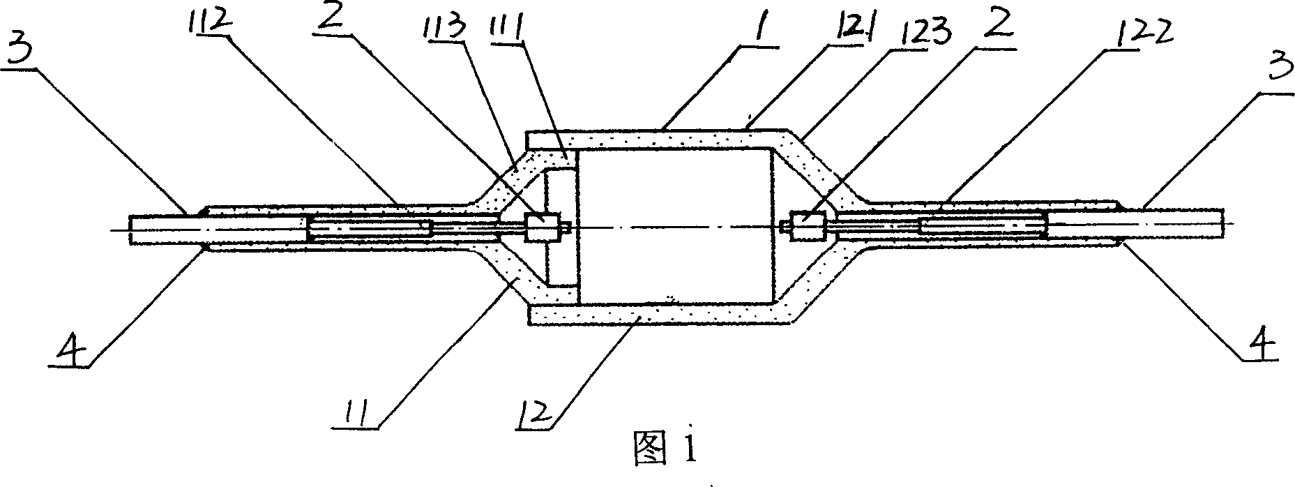
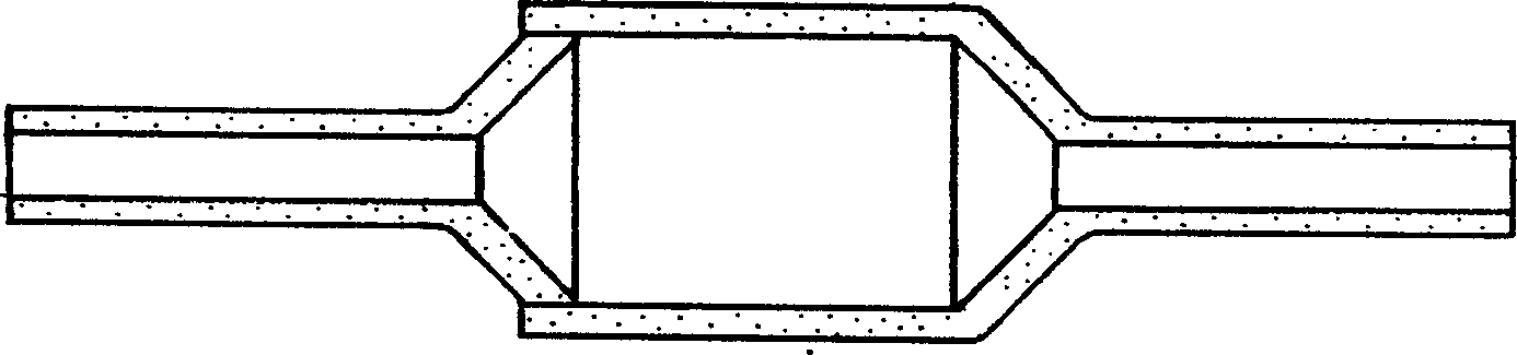
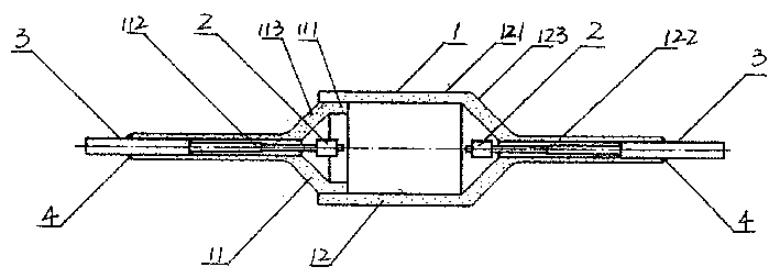
[0015] A metal halide lamp arc tube as shown in Fig. 1 has a casing 1, an electrode 2 is arranged inside the casing 1, a conductive lead 3 is arranged at the rear end of the electrode 2, the casing 1 is made of translucent alumina ceramics, the casing 1 It is formed by sintering a two-piece shell 11 and shell 12. The shell 11 is composed of a thicker cylinder 111, a slender tail pipe 112 and a conical transition tube 113. It is formed by one-time pressing with a mold. The shell 12 and the shell 11 It is similar in shape and consists of three parts: a thicker cylinder 121, a slender tail pipe 122 and a conical transition cylinder 123. It is formed by one-time pressing with a mold. The outer diameter of the thicker cylinder 111 is slightly larger than that of the thicker cylinder. 121, the length of the thicker cylinder 111 is shorter, the electrode 2 is arranged on the conical transition cylinder 113 and the conical transition cylinder 123, and the conductive lead 3 is arranged ...


PUM


Abstract

The present invention relates to an arc tube of metal halide lamp. It has a semitransparent alumina ceramic outer shell, two ends of said outer shell are equipped with a conductive leading wire respectively, and an electrode is mounted on one end of the conductive leading wire nearby cavity body of the outer shell, and the interior of intermediate cavity body is filled with a certain quantity of inert gas, mercury and metal halide of Sc, Na, Tl, In, Dy, Ho and Tm, etc., and said outer shell is made up by using two compacts through sintering process.

Description

Technical field [0001] The invention relates to the electrical industry, in particular to an arc tube of a metal halide lamp. Background technique [0002] At present, the arc tube shells of metal halide lamps in China are all made of quartz glass. Because quartz glass will produce a series of chemical reactions with metal halides at high temperatures and the leakage of metal ions, resulting in the loss of metal elements and electrode damage. Corrosion causes the ignition voltage, arc voltage drop and restart voltage to increase significantly during the use of the lamp, the light decay is large, the light color drifts seriously, and the life is affected, thus limiting the further improvement of the performance and life of the lamp. [0003] Because the chemical stability, corrosion resistance and high temperature resistance of alumina ceramics are significantly better than quartz glass, in recent years, several famous foreign electric light source companies have spent huge s...

Claims


Application Information

Patent Timeline
IPC IPC(8): H01J61/12H01J61/30H01J61/36
Inventor 王凯陈道满
Owner 常州金蓝邑国际贸易有限公司
Why Eureka
Try Eureka