Extensible type hoisting equipment counterweight mechanism

A lifting equipment and counterweight technology, applied in cranes and other directions, can solve the problems that mobile counterweight tower cranes have not been well developed and applied, the development cost of movable counterweight is high, and the moving distance of mobile counterweight is limited. Achieve the effect of facilitating the layout of the tower crane construction site, reducing the influence of adverse torque, and preventing the boom from tilting back.

Active Publication Date: 2016-12-07
韩波
View PDF6 Cites 2 Cited by
  • Summary
  • Abstract
  • Description
  • Claims
  • Application Information

AI Technical Summary

Problems solved by technology

[0004] 1. The static load moment generated when the jib is luffing can only be offset by 20% by the movable counterweight;
[0005] 2. When the boom is large, the lifting capacity will be greatly lost;
[0006] 3. The mobile counterweight jib tower crane consumes a lot of energy and produces noise;
[0007] 4. The movable counterweight mechanism requires additional inspection and maintenance, which is costly; and the development cost of the movable counterweight is also relatively high
[0015] The disadvantage of this method is that this method is only suitable for the case where the lifting weight does not change much, but in fact the lifting weight is random and the range of value changes is large. The adaptability of the crane is not very good, because the position of the counterweight is too sensitive due to the movement with the pitch angle of the boom
Due to the use of the swing counterweight, the tower crane has been greatly improved in the medium and large lifting capacity, which is obviously better than the tower cranes of the same level, and the power consumption is small, but the moving distance of the mobile counterweight is limited.
[0017] To sum up, there are still many limitations in the application of mobile counterweight tower cranes, and after adopting the mobile counterweight method, it has brought many disadvantages, which has led to the failure of mobile counterweight tower cranes. development and application of

Method used


Image

  • Extensible type hoisting equipment counterweight mechanism
  • Extensible type hoisting equipment counterweight mechanism
  • Extensible type hoisting equipment counterweight mechanism

Examples


Embodiment 1

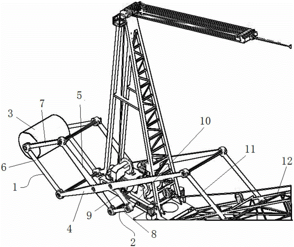
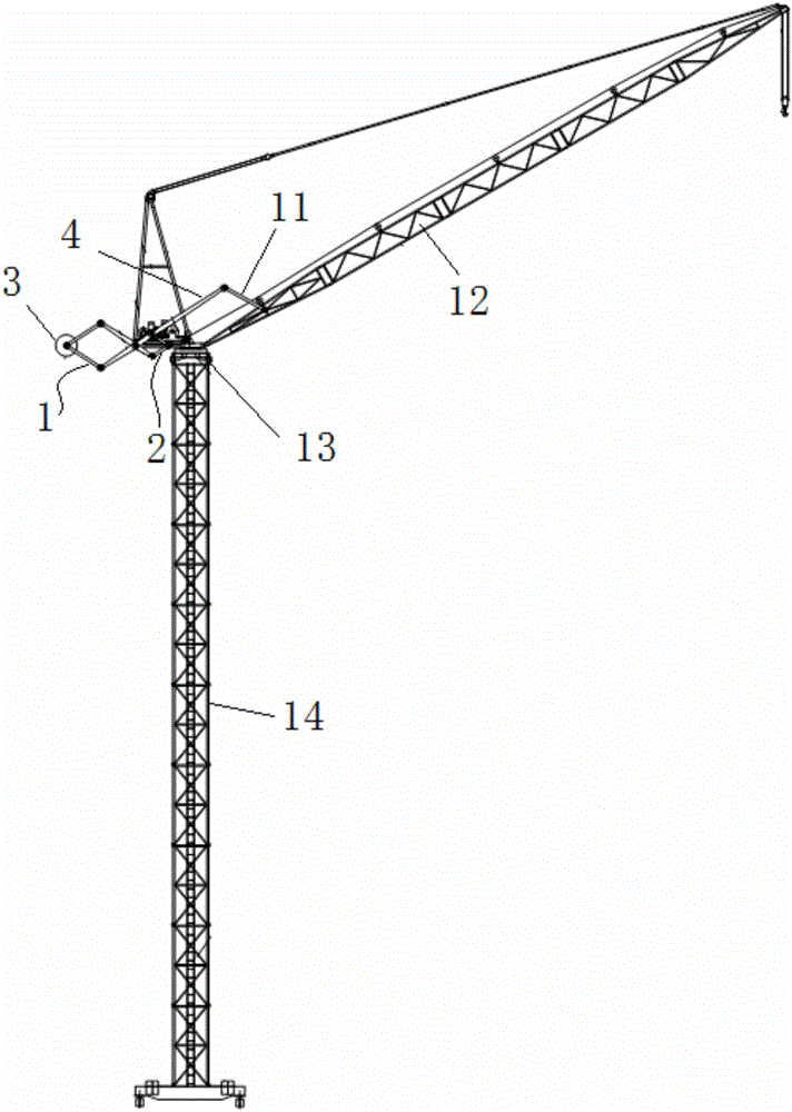
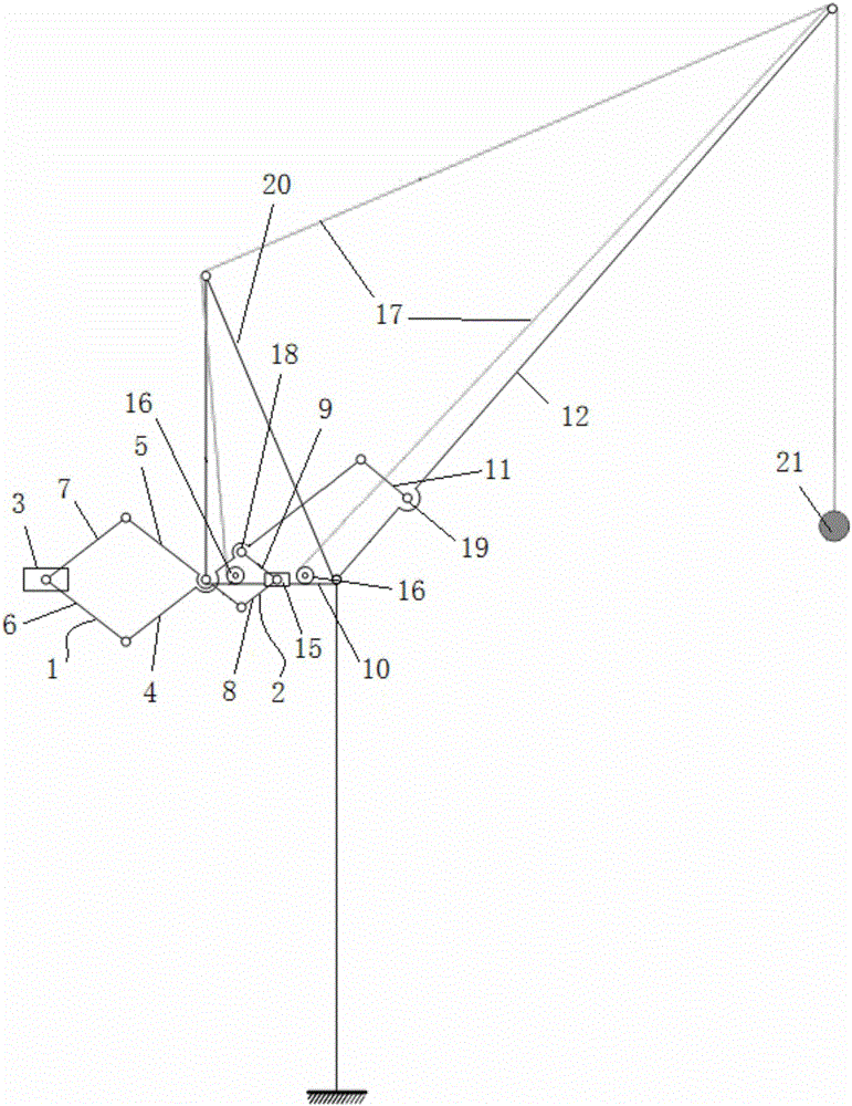
[0055] The hoisting equipment in this embodiment is a tower crane, such as Figure 1~4 As shown, in this embodiment, the hinged ends of the third connecting rod 8 and the fourth connecting rod 9 are slidably connected to the balance arm 10, wherein the hinged ends of the third connecting rod 8 and the fourth connecting rod 9 are provided with There is a slide block 15, which is provided with a slide rail on the balance arm 10, and the slide block 15 moves along the slide rail. This embodiment is provided with a support rod 11, and the drive scissor assembly in the The first scissor bar 4 is provided with an inner extension hinge point 18, such as image 3 As shown, the third connecting rod 8 is hinged to the second scissor bar 5 in the driving scissors assembly, and the fourth connecting rod 9 is hinged to the inner extension hinge on the first scissor bar 4 At point 18, the free end of the first scissor bar 4 is connected to the boom 12 through the support bar 11, and the tw...

Embodiment 2

[0061] The hoisting equipment in this embodiment is a port crane, such as Figure 9 As shown, the main body of the boom 12 of the port crane in the prior art includes a four-link structure, wherein the end hinges of the first boom rod 23 and the second boom rod 24 form a boom link Hinge point 25.

[0062] Such as Figure 10 As shown, in this embodiment, the first boom rod 23 and the second boom rod 24 form a scissor mechanism, and the hinge of the first boom rod 23 and the second boom rod 24 A boom connecting rod hinge point 25 is formed, and the boom connecting rod hinge point 25 is arranged at the connecting end of the balance arm 10 and the tower body 14, wherein the first boom rod 23 exceeds the boom connecting rod The extension part of the hinge point 25 is the third connecting rod 8 connected with the driving scissors assembly, and the extension part of the second boom rod 24 beyond the hinge point 25 of the boom connecting rod is the connecting rod 8 connected with th...

Embodiment 3

[0066] Such as Figure 11 As shown, the difference between this embodiment and Embodiment 2 is that the jib 12 in this embodiment only includes a four-bar linkage mechanism without other structures, and the wire rope goes around the end of the four-bar linkage mechanism away from the tower body 14. Connect with hoisting weight 21 behind the pulley.

[0067] The working principle of this embodiment is:

[0068]When the first boom rod 23 swings, it drives the hoisting weight 21 to move on the one hand, and drives the driving scissors assembly to open and close on the other hand, and then drives the balance weight 3 to move telescopically.


PUM


Abstract

The invention relates to the field of hoisting equipment, in particular to an extensible type hoisting equipment counterweight mechanism. The extensible type hoisting equipment counterweight mechanism comprises an outer extending mechanism, an inner extending mechanism and a driving scissors fork assembly. The driving scissors fork assembly is arranged on a balance arm of hoisting equipment, the outer side of the driving scissors fork assembly is connected with the outer extending mechanism, and the inner side of the driving scissors fork assembly is connected with the inner extending mechanism. A counterweight is arranged at the outer end of the outer extending mechanism. The driving scissors fork assembly is driven to open and close through swinging of a hoisting boom of the hoisting equipment. The driving scissors fork assembly opens and closes to drive the outer extending mechanism to stretch out and draw back. The driving scissors fork assembly drives the inner extending mechanism to open and close. According to the extensible type hoisting equipment counterweight mechanism, the horizontal moving distance of the counterweight is substantially increased by means of the space scaling characteristic of an extensible structure, the balance bending moment of the top of a tower body is effectively reduced, the requirements for stability and static rigidity of a tower crane are met, dynamic performance is more outstanding, materials are saved, power dissipation is reduced, and the hoisting weight of the hoisting equipment is substantially increased.

Description

technical field [0001] The invention relates to the field of lifting equipment, in particular to an extensible balancing weight mechanism of the lifting equipment. Background technique [0002] There has been a long history of research on movable counterweights for lifting equipment. Taking tower cranes as an example, in the 1980s, tower cranes appeared in the form of movable counterweights, which used wire ropes to pull counterweights. In 1985 In 2010, Libherr applied a new type of device to the 500HC tower crane to replace the traditional wire rope moving balance weight method. BKT Company even uses the counterweight mobile device on all types of boom tower cranes above 75t.m, which has a lighter structure and is very beneficial to transportation. In 1989, Potain applied a more complex counterweight moving system to the MR300 tower crane. When the boom is raised, the counterweight moves to the tower through the action of the connecting rod. In 1997, Italy's Comedil (Come...

Claims


Application Information

Patent Timeline
Patent Type & Authority Applications(China)
IPC IPC(8): B66C23/76
CPCB66C23/76
Inventor 韩波陆念力李国荣程立群贾洪涛
Owner 韩波
Why Eureka
Try Eureka