
Barrel plating device and barrel plating automatic production line

A barrel plating and drum technology, applied in the direction of cells, electrolysis process, electrolysis components, etc., can solve the problems of large volume of tank liquid, large exhaust gas discharge, large waste water discharge, etc., and achieve the effect of reducing waste water and reducing consumption.

Inactive Publication Date: 2016-12-07
北京汉昌绿源环保工程有限公司
View PDF7 Cites 7 Cited by
  • Summary
  • Abstract
  • Description
  • Claims
  • Application Information

AI Technical Summary

Problems solved by technology

[0003] Because the drum needs to enter and exit the tank, the amount of bath liquid is taken out (large bath liquid consumption), the solution consumption is large, the waste water discharge is large, the concentration is high, and the exhaust gas discharge is large.

Method used


Image

  • Barrel plating device and barrel plating automatic production line
  • Barrel plating device and barrel plating automatic production line
  • Barrel plating device and barrel plating automatic production line

Examples


Embodiment 1

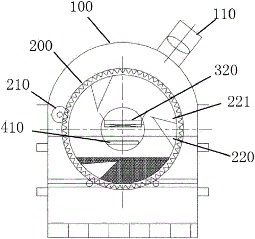
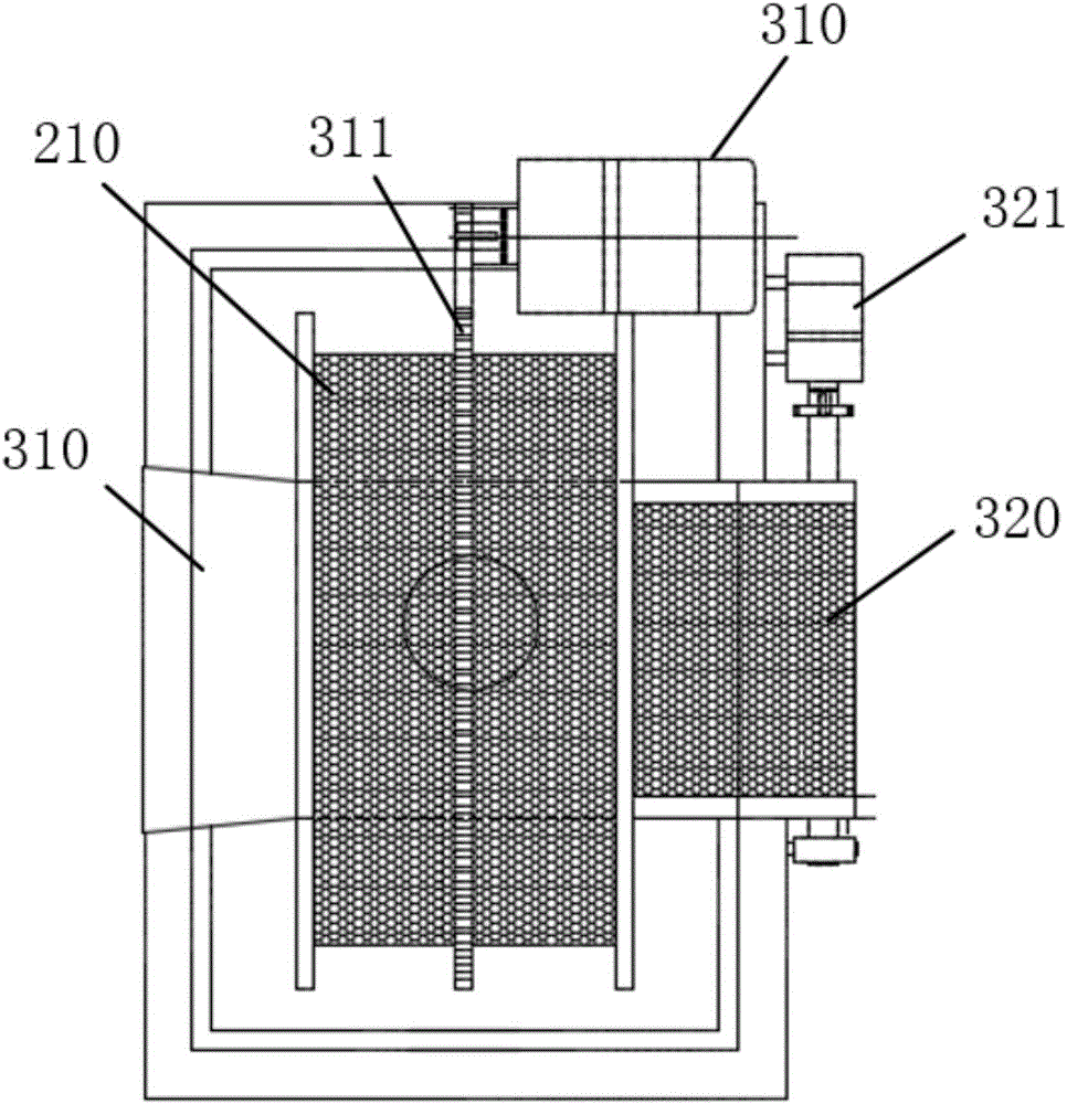
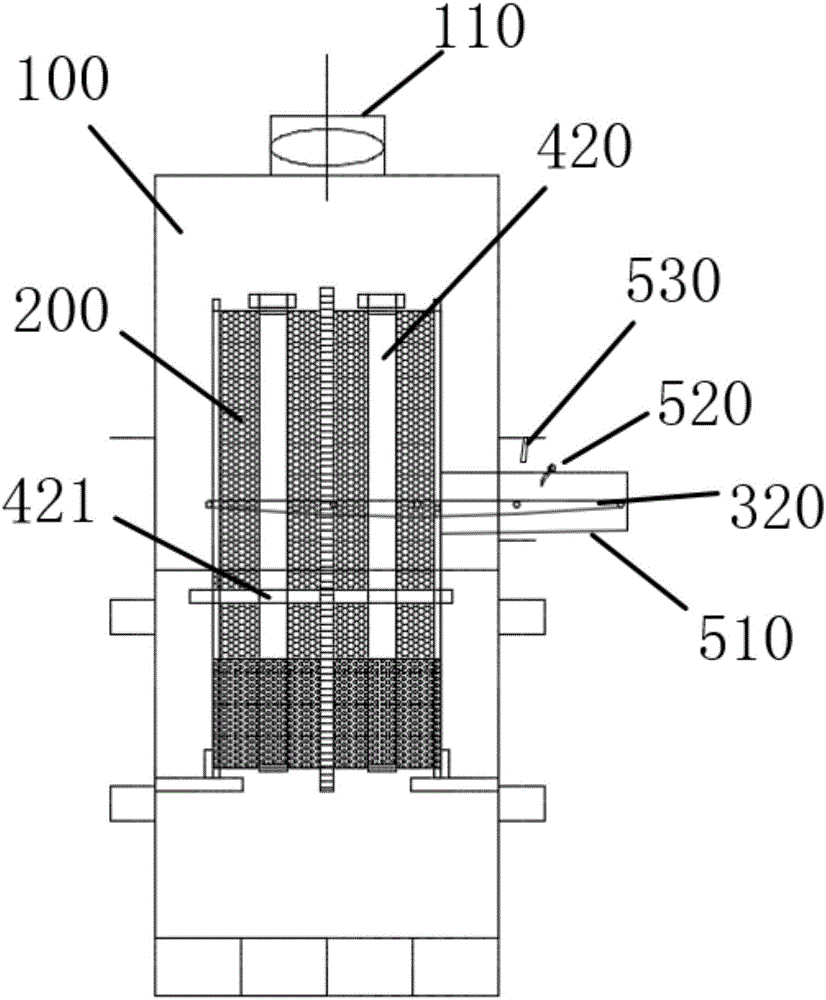
[0041] refer to Figure 1 to Figure 3 , in this embodiment, the barrel plating device provided by the present invention includes: a housing 100, a drum 200 rotatably arranged in the housing 100, a drum motor 210 connected to the drum 200 in transmission, for An input belt for receiving materials and an output belt for outputting materials, the input belt is arranged at the front end of the drum 200 along the axis direction, and the outlet belt is arranged at the rear of the drum 200 along the axis direction end.

[0042] In this embodiment, the rotation of the drum 200 toward the opening of the V-shaped dumping groove 221 is reverse rotation, and vice versa is forward rotation.

[0043] The working principle of the barrel plating device provided in this embodiment is as follows: bath liquid is placed in the housing 100 as required, and the parts enter the drum through the feeding belt and are soaked in the bath liquid. The parts are turned over by the rotation of the drum 20...

Embodiment 2

[0058] refer to Figure 4 , the barrel plating automatic production line provided in this embodiment includes: the chemical degreasing station S100, the hot water washing station S200, the weak corrosion station S300, the first cold water washing station S400, the neutralization station S500, the first The second cold water washing station S600, two cyanide galvanizing stations S700, two cyanide cadmium plating stations S800, and the third cold water washing station S900.

[0059] Each station is provided with the above-mentioned barrel plating device; in any two adjacent stations, the discharge belt of the barrel plating device on the upper station is connected with the input belt of the barrel plating device on the lower station. One or more spraying devices are arranged above the discharge belts of the chemical degreasing station S100 , the hot water washing station S200 and the third cold water washing station S900 . At the same time, on the cyanide galvanizing station S7...


PUM


Abstract

The invention provides a barrel plating device and a barrel plating automatic production line. The barrel plating device comprises a shell, a roller rotationally arranged in the shell, a motor in transmission connection with the roller, a feeding belt used for receiving materials and a discharging belt used for outputting the materials. The feeding belt is arranged at the front end, in the axis direction, of the roller. The discharging belt is arranged at the rear end, in the axis direction, of the roller. According to the barrel plating device and the barrel plating automatic production line, the roller does not need to enter or get out of a trough, the discharging amount of trough liquor is small, consumption is low, and the waste water discharge amount is small.

Description

technical field [0001] The invention relates to electroplating production equipment, in particular to a barrel plating device and an automatic barrel plating production line. Background technique [0002] Standard parts, especially high-strength standard parts, need to be cyanide-galvanized and / or cadmium-plated to increase the corrosion resistance of standard parts, which are mainly used in aerospace, high-speed rail, shipbuilding and other fields. The existing standard parts drum electroplating automatic line adopts the driving mode, and the parts rotate in the drum to realize degreasing, hot water washing, cold water washing, pickling, neutralization, cold water washing, electroplating (cyanide galvanizing or cadmium plating), cold water washing and other processes , driving to realize the drum out of the groove, into the groove and transition between processes. [0003] Because the drum needs to be put into and out of the tank, a large amount of bath liquid is taken out...

Claims


Application Information

Patent Timeline
IPC IPC(8): C25D17/20C25D19/00C25D21/08
CPCC25D17/20C25D21/08
Inventor 佟玮范成荣孙国进李吉丹彭建昌孟庆军
Owner 北京汉昌绿源环保工程有限公司
Learn More