
Single-rod control mechanism

A single-lever control and joystick technology, which is applied to earth movers/shovels, mechanically driven excavators/dredgers, construction, etc. It has the effect of practicability and economy, reducing work intensity and improving reliability

Active Publication Date: 2016-12-07
QINGDAO LOVOL EXCAVATOR
View PDF5 Cites 2 Cited by
  • Summary
  • Abstract
  • Description
  • Claims
  • Application Information

AI Technical Summary

Problems solved by technology

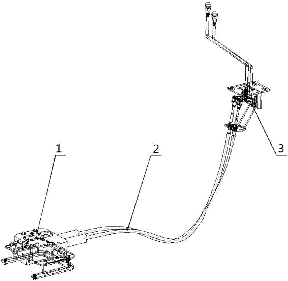
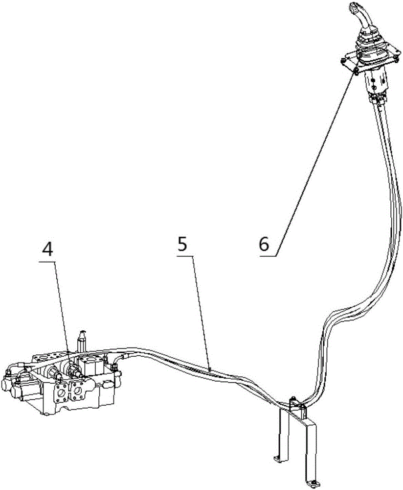
Although in the hydraulic control system, the joystick of the pilot valve can realize multiple functions such as raising and lowering the boom and loading and unloading the bucket shovel through the cross swing of the handle, but according to market feedback, some customer groups prefer the joystick of the mechanical control system. Grip feeling, the recognition of the pilot handle is not high, and the cost of the pilot control mechanism is about 3 to 4 times that of the mechanical control mechanism. If the oil source of the pilot control mechanism (usually a small displacement gear pump) is considered, the cost is relatively high. Mechanical manipulation mechanism adds more

Method used


Image

  • Single-rod control mechanism
  • Single-rod control mechanism
  • Single-rod control mechanism

Examples


Embodiment Construction

[0029] The present invention will be further described below in conjunction with the accompanying drawings and embodiments.

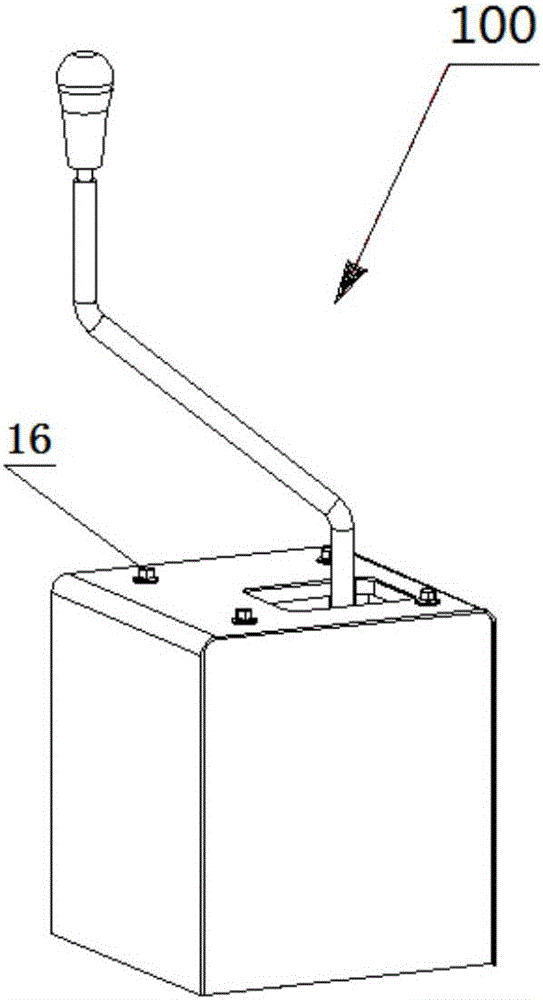
[0030] image 3 It is an assembly schematic diagram of the single-lever operating mechanism provided in the present invention; Figure 4 It is an exploded schematic view of the single-lever operating mechanism provided in the present invention; Figure 5 yes Figure 4 Schematic diagram of the joystick assembly of the single-lever steering mechanism; Image 6 yes Figure 4 Schematic diagram of the bracket assembly of the middle single-lever operating mechanism. Wherein, the direction signs A and B in the accompanying drawings represent up and down, C and D represent front and rear, and E and F represent left and right.

[0031] Such as Figure 3-4 As shown, a single-lever control mechanism 100 includes a control lever assembly 7 , a bracket assembly 8 , a boom bucket handle ball 9 and a protection box 10 . When each assembly of the single-lever op...


PUM


Abstract

The invention provides a single-rod control mechanism. The single-rod control mechanism comprises a control rod assembly, a bracket assembly, a movable arm rotating bucket handle ball and a protection box; the control rod assembly includes a control rod, a welding bracket, a first rocking arm and a second rocking arm; the bottom end of the control rod is welded with a sleeve; the first rocking arm is welded on the sleeve; the second welding arm is welded on the outer side of the welding bracket; the sleeve is mounted on the inner side of the welding bracket through matching a pin shaft with a deep groove ball bearing; the bracket assembly is a three-dimensional square frame built by peripheral brackets and upper and lower plates; a pair of short plates is mounted on the symmetric surfaces of the front and back sides of the frame; a pair of mounting holes is formed in the short plates; the control rod assembly and the bracket assembly are assembled through matching a pin shaft with a deep groove ball bearing; the protection box is fixed on the bracket assembly; and the movable arm rotating bucket handle ball is mounted at the tail end of the control rod. The single-rod control mechanism can realize control of multiple actions through single control rod, and prevents frequent replacement of multiple control rods.

Description

technical field [0001] The invention belongs to engineering machinery, and in particular relates to a single-lever control mechanism that can be widely used in wheeled engineering vehicles. Background technique [0002] For wheeled engineering vehicles, take loaders as an example, the action of its working device is completed by the operating system. Common control systems are mainly divided into mechanical control systems and hydraulic control systems. The difference between the two lies in the way of controlling the multi-way reversing valve. In the mechanical control system, the control mechanism is generally composed of multiple joysticks and control brackets, and the multi-way reversing valve is controlled by pulling the control flexible shaft by the control mechanism; in the hydraulic control system, the control mechanism is generally a pilot valve that can swing crosswise. The multi-way reversing valve is controlled by using the pilot oil of the pilot valve, and the ...

Claims


Application Information

Patent Timeline
Patent Type & Authority Applications(China)
IPC IPC(8): E02F9/20E02F3/43
CPCE02F3/43E02F9/2004
Inventor 尹彦章王桂民王宾陈维雄齐高品夏金玲张健王蓉
Owner QINGDAO LOVOL EXCAVATOR
Learn More