
Apparatus and method for controlling cooling fan speed

A technology of fan speed and cooling fan, which is applied to the components of the pumping device for elastic fluid, pump device, pump control, etc., can solve the problems of increased risk of vehicle fire, unavailable heat energy, and reduced energy efficiency. Risk of fire, improved cooling performance, effects of increased flow velocity

Inactive Publication Date: 2020-01-10
HYUNDAI MOTOR CO LTD
View PDF8 Cites 0 Cited by
  • Summary
  • Abstract
  • Description
  • Claims
  • Application Information

AI Technical Summary

Problems solved by technology

In this case, the thermal energy of the radiation is not available, therefore, its energy efficiency is reduced
In addition, the temperature of the resistors rises up to 555°C, which increases the risk of vehicle fire due to overheating of the resistors

Method used

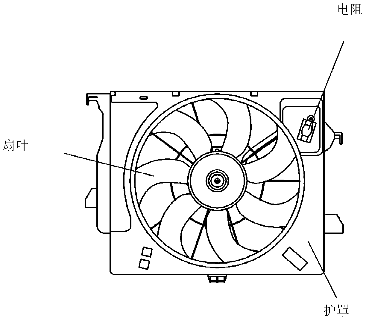
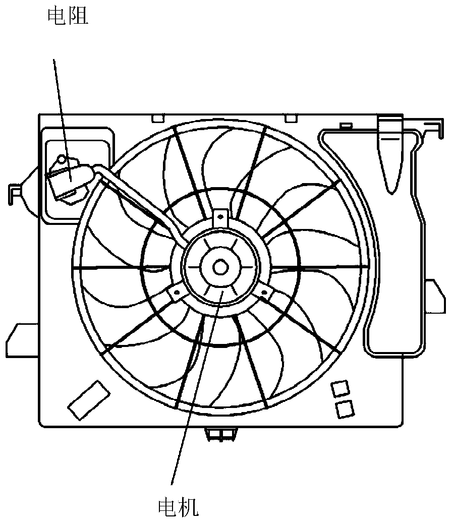
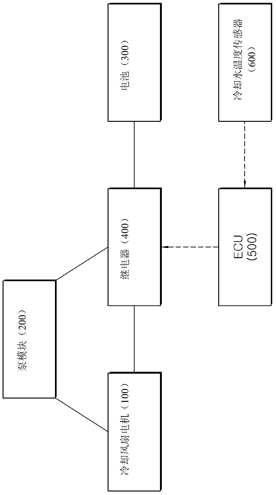

Image

  • Apparatus and method for controlling cooling fan speed
  • Apparatus and method for controlling cooling fan speed
  • Apparatus and method for controlling cooling fan speed

Examples


Embodiment Construction

[0028] Based on the principle that the inventor can properly define the concept of terms in order to best explain his invention, the words and terms used in the specification and claims are not limited to the general or dictionary meanings, but should be interpreted in accordance with Meanings and concepts consistent with the technical thought of the present invention. Because the embodiment described in this description and the structure shown in the accompanying drawings are only the most ideal embodiments of the concept of the present invention, and do not present all the technical ideas in the concept of the present invention, it should be understood that the implementation of the present application From time to time, there may be various equivalent forms and conversion examples instead of these embodiments of the present invention. Also, detailed descriptions about well-known functions and constructions that would unnecessarily obscure the gist of the application may be ...


PUM


Abstract

The present application discloses a device and method for controlling the rotation speed of a cooling fan, wherein the device for controlling the rotation speed of a cooling fan includes: a cooling fan motor that runs the cooling fan; a pump that is connected in series to the cooling fan motor; a relay, One side of it is connected to the cooling fan motor or the pump, and the other side is connected to the battery, so that the power of the battery can be supplied to either of the cooling fan motor or the pump.

Description

[0001] Cross References to Related Applications [0002] This application claims the benefit of priority from Korean Patent Application No. 10-2014-0162535 filed on November 20, 2014, the entire contents of which are incorporated herein by reference. technical field [0003] The present application relates to an apparatus and method for controlling the rotational speed of a cooling fan, and more particularly, to an apparatus and method for controlling the rotational speed of a cooling fan by using a pump. Background technique [0004] The temperature of the internal combustion engine of the vehicle increases as the vehicle runs, and the hot engine is usually cooled by an air cooling method or a water cooling method. The air cooling method allows the engine to be exposed to the atmosphere without additional assistance, which avoids cooling water freezing and leakage, etc. However, when the temperature of the outside air is high or the vehicle is parked temporarily, the cooli...

Claims


Application Information

Patent Timeline
Patent Type & Authority Patents(China)
IPC IPC(8): F01P7/04F01P7/08F01P7/16F01P5/04F01P5/12
CPCF04D5/00F04D27/004F01P7/048F01P7/026F04D19/002F04D13/068F04D25/0673Y02B30/70F01P1/06F01P3/20F01P5/04F01P5/12F04D1/00F04D29/22F04D29/325
Inventor 金炅兑
Owner HYUNDAI MOTOR CO LTD
Learn More