
Patsnap Eureka
For R&D, Patsnap Eureka makes reading and utilizing patents & technical documents easy.
Patsnap Eureka AIR
Designed for self-driven R&D workflows. Generate viable solutions, solve complex R&D challenges, empower your innovation with AI.

Patsnap Eureka Materials
Designed for material experts only. Revolutionize your material R&D, from search, analyze, to developing new materials.

TechResearch
Generate reliable direction feasibility study reports for your R&D in just a few steps.

TechSeek
Discover and master advanced knowledge NOW. Basics, ideas, possibilities, all at once.

TechMind
As an expert in R&D Theories, TechMind can generates customized viable solutions instantly.

TechRisk
Analyze your overall solution with one click, know your potential R&D risks in advance.

TechMonitor
Get weekly tech updates, stay abreast of the latest tech innovations and key insights.
Apparatus for reducing oil leakage in two-stage turbocharger
A turbocharger and supercharger technology, which is applied in the lubrication of turbine/propulsion devices, gas turbine devices, engines, etc., and can solve problems such as lubricating oil leakage
- Summary
- Abstract
- Description
- Claims
- Application Information
AI Technical Summary
Problems solved by technology
Method used
Image

Examples
Embodiment Construction
[0016] An apparatus for reducing lubricant oil leakage in a two-stage turbocharger according to an exemplary embodiment of the present invention, an example of which is shown in the accompanying drawings, will now be described in more detail. Also, the same reference numerals will be used throughout the drawings and specification to refer to the same or like parts.
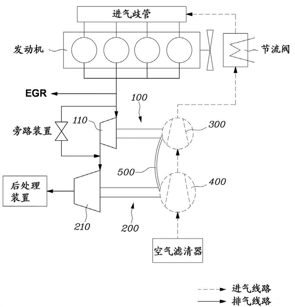
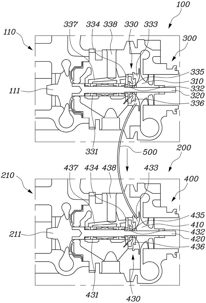
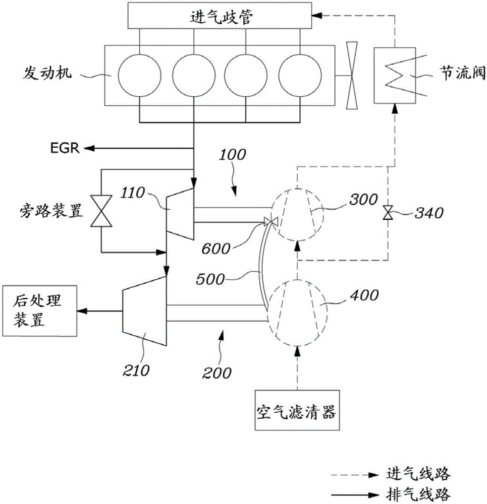
[0017] figure 1 To show a schematic structural view of an exemplary embodiment of an apparatus for reducing lubricating oil leakage in a two-stage turbocharger according to the present invention, figure 2 for figure 1 A detailed view of the transmission side of the middle.
[0018] The apparatus for reducing lubricating oil leakage in a two-stage turbocharger according to the present embodiment includes a transmission part 500 connecting the high-pressure turbocharger 100 to the low-pressure turbocharger 200 so that clean air ( Pressurized air between the back of the compressor wheel and the bearing housing ba...
PUM
 Abstract
Description
Claims
Application Information
 - R&D Engineer
- R&D Manager
- IP Professional
- Industry Leading Data Capabilities
- Powerful AI technology
- Patent DNA Extraction
Browse by: Latest US Patents, China's latest patents, Technical Efficacy Thesaurus, Application Domain, Technology Topic, Popular Technical Reports.
© 2024 PatSnap. All rights reserved.Legal|Privacy policy|Modern Slavery Act Transparency Statement|Sitemap|About US| Contact US: help@patsnap.com