Gap sealing structure and bearing

A sealing structure and gap technology, applied in the field of thrust bearings, can solve the problems of no way to reduce the friction force of thrust bearings, can not completely prevent air infiltration, can not save electric energy for a long time, etc., to achieve large axial force, radial stability, low noise small effect

Active Publication Date: 2019-04-19
张晓春
View PDF5 Cites 0 Cited by
  • Summary
  • Abstract
  • Description
  • Claims
  • Application Information

AI Technical Summary

Problems solved by technology

At this stage, the problem with large-capacity flywheel energy storage batteries is that they cannot store electrical energy for a long time, because there is no way to reduce the friction of thrust bearings, especially the friction of thrust bearings with large axial forces generated by large-mass flywheels. As a result, it is impossible to realize the process of the flywheel rotating, and maintain the speed for a long time with little consumption. How to reduce the bearing loss, wind friction loss and no-load loss during the operation of the flywheel has become the key to high efficiency and long-term energy storage of a large-energy flywheel. question
[0006] Although the characteristic of gas itself is also fluidity, compared with liquid, it does not conform to Pascal's law, that is, the pressure will be equal to any place that the gas can reach, and finally keep the pressure of any place equal. Unable to completely prevent air infiltration
[0007] Due to the fluid's own characteristics, that is, fluidity and incompressibility, the interface between the fluid and the fluid, and the fluid and the solid can be matched indefinitely, but it is precisely because of the fluidity that the fluid will follow the pressure. Direction flow, which makes it impossible for the fluid to be used as a sealing body alone to realize the function of gap sealing under the traditional method. Taking lubricating oil as an example, it usually requires extra work to put the lubricating oil in the corresponding sealing position.

Method used


Image

  • Gap sealing structure and bearing
  • Gap sealing structure and bearing
  • Gap sealing structure and bearing

Examples


Embodiment Construction

[0046] In order to enable those skilled in the art to better understand the present invention, the present invention will be further clearly and completely described below in conjunction with reference to the accompanying drawings and in conjunction with embodiments. It should be noted that, in the case of no conflict, the embodiments in the present application and the features in the embodiments can be combined with each other.

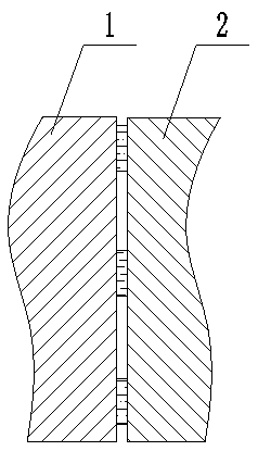
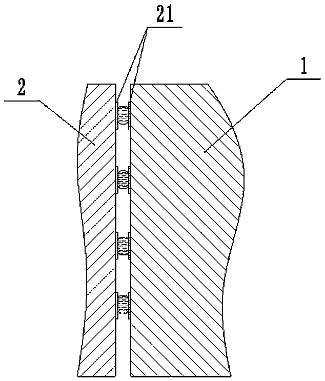
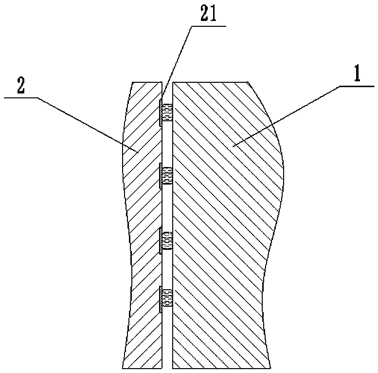
[0047] like figure 1 The gap sealing structure shown includes: a fluid and a holding structure, the fluid forms at least one gap seal in the gap between the walls of the moving body 1 and the static body 2 to be sealed; the holding structure is arranged on one of the moving body 1 and the static body 2 One or two walls are used to keep the fluid in the predetermined sealing position, restrict the movement of the fluid and form a fluid sealing ring between the walls.

[0048] On this basis, the present invention further utilizes the relationship betw...


PUM


Abstract

The invention relates to a simple clearance seal structure. The structure comprises fluid and a keeping structure; the fluid forms at least one clearance seal in a clearance of the wall faces, required to be sealed, of a movable body and a fixed body; the keeping structure is arranged on the wall face of one or two of the movable body and the fixed body and is used for enabling the fluid to be kept on the preset seal portion to limit the fluid, and a fluid seal ring is formed between the wall faces; on the basis of a seal structure, the invention further relates to a thrust bearing and an energy storage pond with the thrust bearing. A bearing shaft ring is coaxially inserted into and sleeved with a shaft base, the clearance seal is arranged between the outer wall face of the shaft ring and the opposite wall face of the shaft base, and a clearance cavity is formed between two or more fluid seal rings. The seal structure is simple and good in seal performance; and the thrust bearing has the beneficial effects of being low in wear, large in axial bearing force, stable in radial direction and good in seal performance.

Description

technical field [0001] The invention relates to a sealing structure, in particular to a gap sealing structure applied to a bearing and a thrust bearing based on the fluid sealing mechanism. Background technique [0002] In addition to the mechanical contact friction method, the general sealing method, which has less energy consumption and relatively small friction force, is generally a magnetic fluid seal, but there are defects such as high cost, difficult processing, complex structure, eddy current loss, heat generation, and inability to withstand high temperatures. . [0003] The demand for bearings is very extensive, and it is a key mechanical basic part for the development of the national economy, and its importance is self-evident. Wear and drag are inherent disadvantages of mechanical contact bearings, especially thrust bearings. At present, the method to achieve lower loss is the superconducting magnetic levitation thrust bearing, but the problems of high cost, comp...

Claims


Application Information

Patent Timeline
Patent Type & Authority Patents(China)
IPC IPC(8): F16C33/74F16C17/08F16J15/40H02K7/02
CPCY02E60/16
Inventor 张晓春张皓魏进利杨四平张学仁
Owner 张晓春
Why Eureka
Try Eureka