Cam-type hydraulic polishing machine

A grinding machine, cam type technology, applied in the direction of grinding frame, grinding machine parts, grinding/polishing equipment, etc. The quality and efficiency of polishing can achieve the effect of small pressure loss, stable axial force and less heat generation.

Pending Publication Date: 2018-12-25
LANZHOU UNIVERSITY OF TECHNOLOGY
View PDF0 Cites 0 Cited by
  • Summary
  • Abstract
  • Description
  • Claims
  • Application Information

AI Technical Summary

Problems solved by technology

Because the applied axial force is not easy to control, it causes the grinding and polishing disc to vibrate during medium and high-speed rotation. It is not easy to control the rotation angle of the workpiece when changing the sandpaper, and there is no treatment for the grinding debris, which affects the polishing. quality and efficiency

Method used


Image

  • Cam-type hydraulic polishing machine
  • Cam-type hydraulic polishing machine
  • Cam-type hydraulic polishing machine

Examples


Embodiment Construction

[0016] The technical solutions in the embodiments of the present invention are described in detail below with reference to the drawings in the embodiments of the present invention. The embodiments described here are only used to illustrate and explain the present invention, not to limit the present invention.

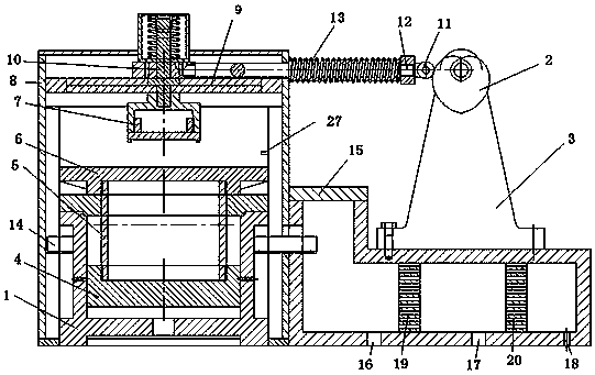
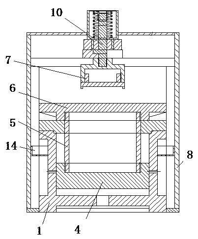
[0017] like figure 1 and figure 2 As shown, a kind of cam type metallographic polishing machine provided by this embodiment includes a frame 8, a piston cylinder 1 is arranged inside the frame 8, and a driving cam 2 is arranged outside the frame 8, and the driving cam 2 is arranged on the outside of the frame 8. The cam 2 is fixed on the cam bracket 3, and a roller 11 is arranged on one side of the driving cam 2, and the roller 11 is installed on a roller pole 12, and a second wheel pole 12 is arranged between the roller pole 12 and the frame 8. A spring 13, the first spring 13 is set on the roller rod 12, the piston 4 is installed in the piston cylinder 1, the conne...


PUM


Abstract

The invention discloses a cam-type metallographic polishing machine. The polishing machine comprises a rack, a piston cylinder is arranged in the rack, a driving cam is arranged on the outer side of the rack and fixed to a cam bracket, a roller is disposed on one side of the driving cam and mounted on a roller support rod, a first spring is disposed between the roller support rod and the rack andsleeves the roller support rod, a piston is mounted in the piston cylinder, a connecting cylinder is fixedly mounted on the piston, a working platform is fixedly mounted above the connecting cylinder,sandpaper is mounted on the working platform, and a guide rail is mounted on the top of the rack; a clamp is disposed above the working platform and fixed to a clamp rod, and the clamp rod is connected with a sliding pair of the guide rail and fixedly connected with the roller support rod. The polishing machine can achieve recycling of water, metal polishing shreds can be preliminary treated, thepracticability is high, the cost is low, and mass production and wide application are facilitated.

Description

technical field [0001] The invention relates to the field of polishing machines, in particular to a cam type metallographic polishing machine. Background technique [0002] At present, in the process of metallographic sample preparation at home and abroad, after cutting and sampling, preliminary pre-grinding, rough grinding, fine grinding, semi-finish polishing, fine polishing and cleaning and drying are carried out in sequence. With the development of material analysis and inspection technology, higher requirements are put forward for the preparation of metallographic samples, and the traditional manual polishing can no longer meet the requirements. The polishing process is a processing procedure before polishing, and the polishing quality greatly affects the polishing quality. When the existing polishing machine or polishing machine performs polishing work, the workpiece is usually fixed, and an axial force is applied to the workpiece by mechanical or manual adjustment, a...

Claims


Application Information

Patent Timeline
Patent Type & Authority Applications(China)
IPC IPC(8): B24B7/10B24B41/02B24B41/06B24B47/22B24B55/02B24B55/12
CPCB24B7/10B24B41/02B24B41/06B24B47/22B24B55/02B24B55/12
Inventor 宋伟尘强刘荣敏于博何贞君李万佳任志祥张雪冬
Owner LANZHOU UNIVERSITY OF TECHNOLOGY
Why Eureka
Try Eureka