Tensioner

A technology of tensioning device and sleeve, applied in the direction of transmission device, belt/chain/gear, mechanical equipment, etc., to achieve the effect of suppressing skew and easy forming

Inactive Publication Date: 2019-04-12
TSUBAKIMOTO CHAIN CO
View PDF10 Cites 0 Cited by
  • Summary
  • Abstract
  • Description
  • Claims
  • Application Information

AI Technical Summary

Problems solved by technology

[0005] In the tensioner 510 as described above, there is a problem that since the tensioner body 520 is a die-cast product of cast iron or aluminum alloy, in order to prevent the plunger 540 from being worn and sintered, in order to obtain a body in which the plunger 540 slides The surface accuracy and durability of the cylindrical hole 521 require film formation by coating treatment, smoothing treatment, machining, etc.

Method used


Image

  • Tensioner
  • Tensioner
  • Tensioner

Examples


Embodiment Construction

[0035] Hereinafter, the tension device 10 according to the first embodiment of the present invention will be described with reference to the drawings.

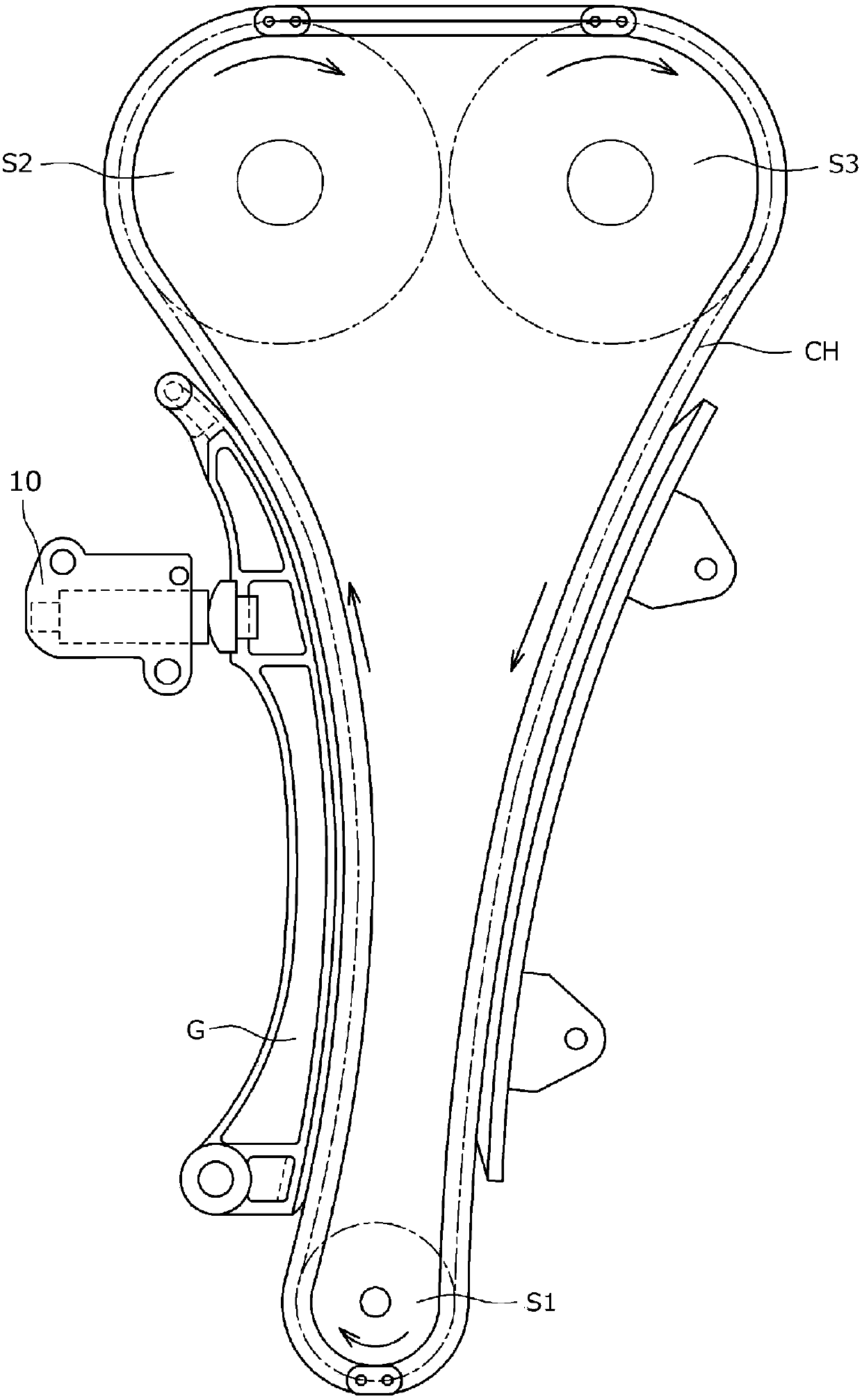
[0036] First, the tensioner 10 of the present embodiment is mounted on a chain transmission used in a timing system of an automobile engine, etc., such as figure 1 As shown, it is installed on the engine body (not shown), and through the tensioner rod G, an appropriate tension is applied to the slack side of the transmission chain CH that is rotatable on the multiple sprockets S1-S3, and the vibration during movement is suppressed. .

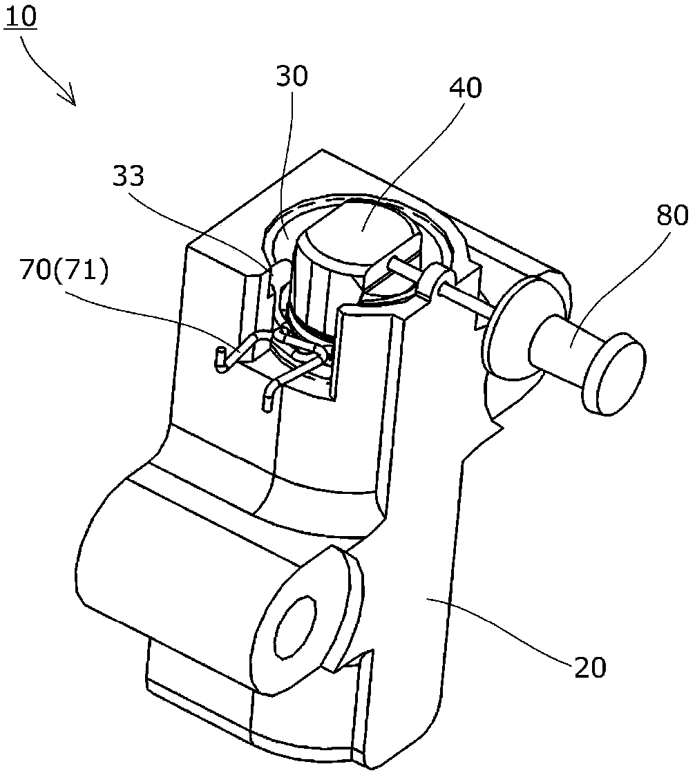
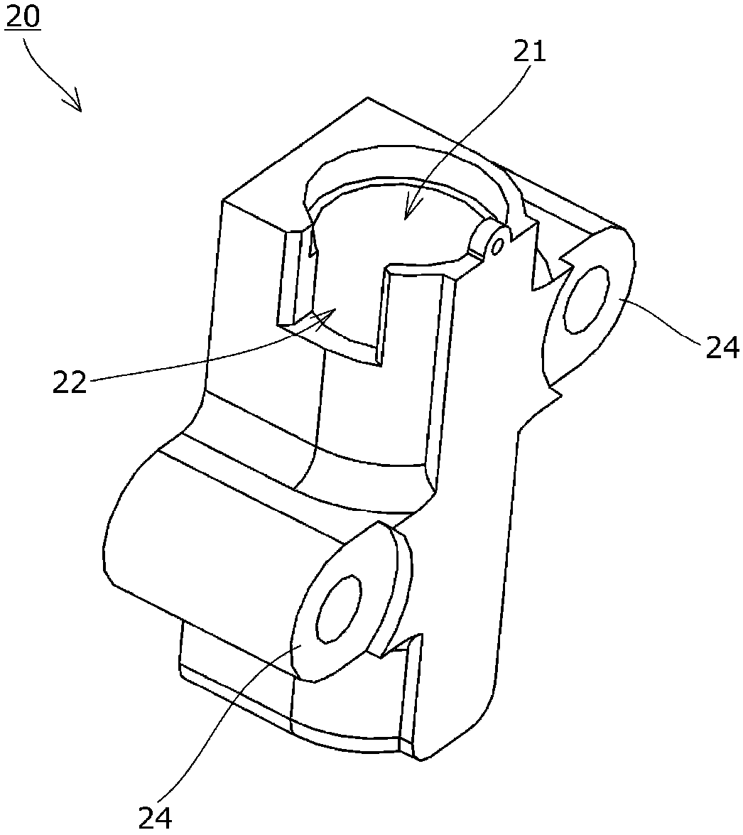
[0037] Such as Figure 2 to Figure 7 As shown, the tensioning device 10 has: a tensioning device main body 20 having a cylindrical hole 21 of the main body; a sleeve 30 inserted into the cylindrical hole 21 of the main body; It is inserted into the sleeve 30 to move forward and backward; the check valve 50 is arranged in the plunger 40; The pressure oil chamber 11 in between exerts force on ...


PUM


Abstract

To provide a simple-structured tensioner that can maintain good sliding properties of and hydraulic pressure for the plunger. The tensioner 10 includes a sleeve 30 inserted into a cylindrical body hole 21, a plunger 40 inserted in the sleeve 30 such as to be able to advance and retract along an axial direction of the sleeve 30, and biasing unit 60 for biasing the plunger 40 toward a front side. The sleeve 30 has, at a front end of a sleeve body 31 thereof, a flange part 33 extending radially outward.

Description

technical field [0001] The present invention relates to a tensioning device for applying proper tension to a moving chain or belt or the like. Background technique [0002] Conventionally, a tensioner is generally used in order to properly maintain the tension of a chain or the like. For example, there is known a technique in which a tensioner rod is provided between sprockets of a crankshaft and a camshaft respectively provided in an engine room (engine room). In a chain guide mechanism in which a transmission chain such as a roller chain that rotates without joints is slide-guided, a tensioner is used to apply force to the tensioner rod in order to properly maintain the tension of the chain, etc. [0003] For example Figure 10 As schematically shown, a known tensioner 510 used in the above-mentioned chain guide mechanism includes: a tensioner body 520 having a body cylindrical hole 521 opened on one side; a plunger 540 slidably inserted into the The main body cylindrical...

Claims


Application Information

Patent Timeline
Patent Type & Authority Patents(China)
IPC IPC(8): F16H7/08
CPCF16H7/08F16H2007/0802F16H7/0836F16H2007/0814F16H2007/0859F16H2007/0878F16H2007/0893F16H2007/0812F16H2007/0876
Inventor 石川祐一郎国松幸平
Owner TSUBAKIMOTO CHAIN CO
Why Eureka
Try Eureka