
External circulation system for CFB smoke generation equipment

A circulation system and flue gas generation technology, applied in the field of external circulation system, can solve the problems of large bed area, difficulty in large-scale, low flue gas velocity, etc.

Inactive Publication Date: 2016-12-07
自贡华西能源工业有限公司
View PDF7 Cites 0 Cited by
  • Summary
  • Abstract
  • Description
  • Claims
  • Application Information

AI Technical Summary

Problems solved by technology

The equipment in the form of bubbling bed has low flue gas velocity and large bed surface area, making it difficult to scale up

Method used


Image

  • External circulation system for CFB smoke generation equipment
  • External circulation system for CFB smoke generation equipment
  • External circulation system for CFB smoke generation equipment

Examples


Embodiment 1

[0018] An external circulation system for CFB flue gas generating equipment, comprising an adiabatic gas-solid rotary separator 2 and a feeder 4 arranged at the bottom thereof and communicating with it.

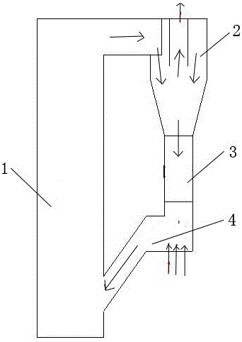
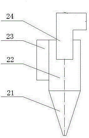
[0019] The adiabatic gas-solid rotary separator 2 is as figure 2 As shown, the main body is divided into an upper straight section 22 and a lower cone section 21, the side of the straight section 22 is provided with a flue gas inlet 23, and a central cylinder 24 is vertically arranged in the straight section 22, and the upper port of the central cylinder 23 is For flue gas outlet. The flue gas inlet 23 draws air from the flue gas outlet at the top of the combustion furnace 1, and the feeder 4 returns the collected solid particles to the combustion chamber of the combustion furnace 1 for re-combustion.

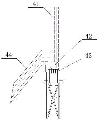
[0020] The feeder 4 is as image 3 As shown, it includes a feed pipe 41, a return valve 42 and a discharge pipe 44. The upper part of the feed pipe 41 communicates with the...

Embodiment 2

[0023] like figure 1 As shown, an external circulation system for CFB flue gas generating equipment includes an adiabatic gas-solid rotary separator 2 and a feeder 4 arranged at its bottom and communicated with it through a feed pipe 3 .

[0024] The adiabatic gas-solid rotary separator 2 is as figure 2 As shown, the main body is divided into an upper straight section 22 and a lower cone section 21, the side of the straight section 22 is provided with a flue gas inlet 23, and a central cylinder 24 is vertically arranged in the straight section 22, and the upper port of the central cylinder 23 is For flue gas outlet.

[0025] The feeder 4 is as image 3 As shown, it includes a feed pipe 41, a return valve 42 and a discharge pipe 44. The upper part of the feed pipe 41 communicates with the bottom of the adiabatic gas-solid rotary separator 2, and the return valve 42 is installed on the feed pipe 41. Bottom, and a number of air caps 43 leading to the outside are installed in ...


PUM


Abstract

The invention discloses an external circulation system for CFB smoke generation equipment. The external circulation system for the CFB smoke generation equipment comprises a heat-insulating gas-solid rotary separator and a return feeder which is arranged at the bottom of the heat-insulating gas-solid rotary separator and communicates with the heat-insulating gas-solid rotary separator through a return pipe. A main body of the heat-insulating gas-solid rotary separator is divided into a straight section on the upper portion and a conical section on the lower portion. A smoke inlet is formed in the side portion of the straight section. A center cylinder is vertically arranged in the straight section. The upper end opening of the center cylinder is a smoke outlet. According to the external circulation system for the CFB smoke generation equipment, solid particles are separated out and collected through the heat-insulating gas-solid rotary separator and then conveyed and returned back into a combustion hearth through the return feeder so as to be combusted and used again, and the fuel utilization rate and heat efficiency are improved while the smoke quality is improved.

Description

technical field [0001] The invention relates to an external circulation system used for CFB flue gas generating equipment, belonging to the technical field of combustion equipment. Background technique [0002] CFB flue gas generating equipment, which uses coal combustion to generate flue gas as a process medium, has a wide range of functions in the field of industrial production and drying. [0003] At present, the CFB flue gas generating equipment operating in China is relatively small, and its capacity is generally below 20MW. The furnace types include chain furnace, pulverized coal furnace, fluidized fluidized furnace, bubbling bed and other forms. The equipment in the form of chain furnace, due to the coal leakage of the grate, causes incomplete combustion, large heat loss and low thermal efficiency. For equipment in the form of pulverized coal furnace, it is difficult to collect fly ash, and it is difficult to guarantee the quality of flue gas, and the pulverization ...

Claims


Application Information

Patent Timeline
Patent Type & Authority Applications(China)
IPC IPC(8): F23C10/26
Inventor 蔡文钢郑军陈金火
Owner 自贡华西能源工业有限公司
Learn More