Plasma ignition system, control method, and applicable ultra-supercritical boiler

An ultra-supercritical boiler and plasma ignition technology, applied in the field of boiler ignition, can solve problems such as power waste and energy loss in the plant

Inactive Publication Date: 2016-12-07
JIANGSU DATANG INT LUSIGANG POWER GENERATION
View PDF7 Cites 8 Cited by
  • Summary
  • Abstract
  • Description
  • Claims
  • Application Information

AI Technical Summary

Problems solved by technology

Since the plasma ignition device has been in an emergency standby state during the normal operation of the unit, its cooling fan has been running continuously, resulting in waste of plant power and energy loss

Method used


Image

  • Plasma ignition system, control method, and applicable ultra-supercritical boiler
  • Plasma ignition system, control method, and applicable ultra-supercritical boiler
  • Plasma ignition system, control method, and applicable ultra-supercritical boiler

Examples


Embodiment 1

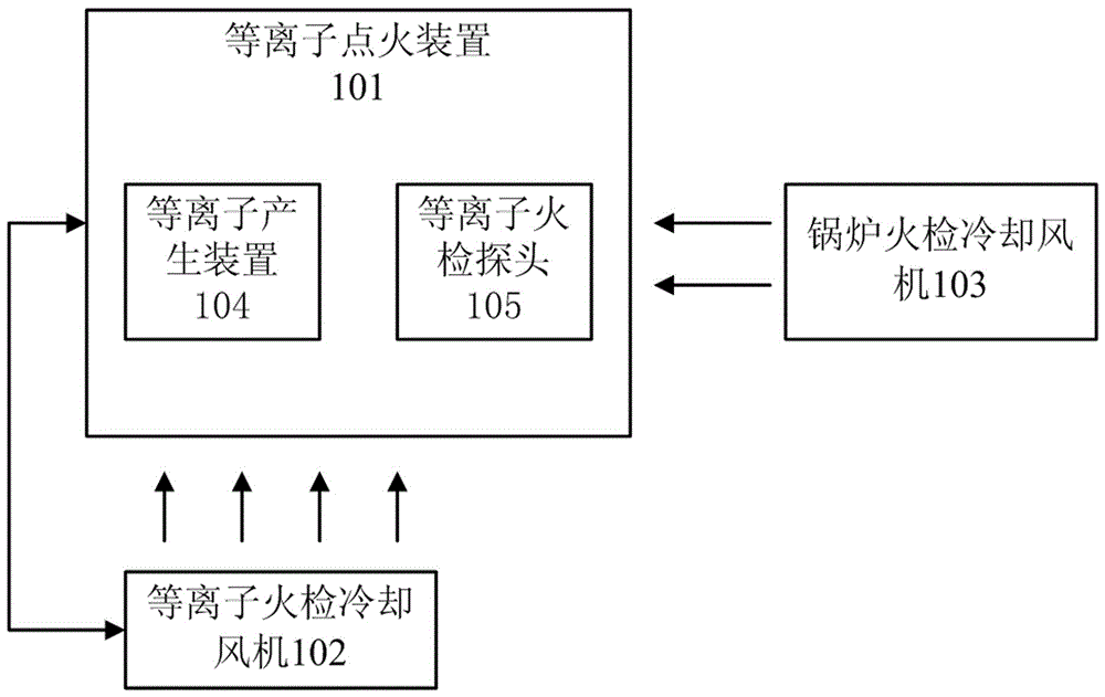
[0026] Such as figure 1 As shown, the present invention discloses a first embodiment of a plasma ignition system. The plasma ignition system includes: a plasma ignition device 101 , a plasma flame detector cooling fan 102 and a boiler flame detector cooling fan 103 .

[0027] The plasma ignition device 101 includes an ignition burner (not shown in the figure), a plasma generating device 105 and a plasma flame detection probe 105 arranged corresponding to the ignition burner.

[0028] The input end of the plasma ignition detection cooling fan 102 is communicatively connected to the plasma ignition device 101 , and the air is directed toward the plasma generation device 102 . When the plasma ignition device 101 is ignited, and the plasma generating device 102 is started, the plasma fire detection cooling fan 102 is triggered to start work, and the plasma carrier wind is provided for the plasma generating device 105;

[0029] The plasma flame detection cooling fan 102 has a flow...


PUM


Abstract

The invention discloses a plasma ignition system which comprises a plasma ignition device, a plasma flame detection cooling fan and a boiler flame detection cooling fan, wherein the plasma ignition device comprises an ignition burner, a plasma generation device and a plasma flame detection probe; the plasma generation device and the plasma flame detection probe are arranged corresponding to the ignition burner; the input end of the plasma flame detection cooling fan is in communication connection with the plasma ignition device; the plasma flame detection cooling fan blows wind towards the plasma generation device; when the plasma ignition device and the plasma generation device are started up, the plasma flame detection cooling fan is triggered to start working and to supply plasma carrier wind; when the plasma generation device is shut down, the plasma flame detection cooling fan is controlled to stop working; and the boiler flame detection cooling fan is kept in a normally open state and blows wind towards the plasma flame detection probe. According to the plasma ignition system disclosed by the invention, the plasma flame detection cooling fan and the plasma ignition device are started up and shut down in a linked manner, thereby reducing the equipment operation, lowering the energy consumption, and reducing the maintenance.

Description

technical field [0001] The invention relates to boiler ignition technology, in particular to a plasma ignition system, a control method and an applicable ultra-supercritical boiler. Background technique [0002] In recent years, due to the continuous tension in the demand for traditional boiler fuels such as coal, oil, and natural gas, and the continuous rise in prices, the cost of fuel oil for commissioning and operation has been rising steadily. In order to reduce diesel consumption, most thermal power plants in my country have introduced plasma ignition systems to reduce commissioning and operating fuel costs. However, in this era of increasingly fierce competition, energy saving for enterprises is particularly important. The problem of energy consumption is particularly prominent. [0003] The plasma ignition device uses direct current to contact the arc under the condition of medium pressure 0.004 MPa ~0.03 MPa, and obtains stable power of direct current air plasma unde...

Claims


Application Information

Patent Timeline
Patent Type & Authority Applications(China)
IPC IPC(8): F23Q7/04F23Q7/22
CPCF23Q7/04F23Q7/22
Inventor 刘进峰刘青松商执晋陈捷刘炜施以文孙杰祁永峰王奇
Owner JIANGSU DATANG INT LUSIGANG POWER GENERATION
Why Eureka
Try Eureka