System for heating soil bodies around underground cryogenic storage tank

A low-temperature storage tank and surrounding soil technology, which is applied in heating methods, air conditioning systems, lighting and heating equipment, etc. Utilization, ensure uniform heating effect

Active Publication Date: 2016-12-07
SHAOXING UNIVERSITY
View PDF9 Cites 1 Cited by
  • Summary
  • Abstract
  • Description
  • Claims
  • Application Information

AI Technical Summary

Problems solved by technology

[0005] In view of the above existing problems, the present invention provides a system for heating the soil around the underground low-temperature storage tank to overcome the problems of low energy conversion rate and uneven heating of the soil caused by heating with electric heating rods in the prior art. The heat pump air conditioner, buried pipe and connecting main pipe are used in the system of heating the soil around the underground low temperature storage tank. The circulating water heated by the ground source heat pump air conditioner is used as the heat source to heat the rock and soil around the underground low temperature storage tank through the buried pipe. , at the same time, the buried pipe converts the circulating water and the rock and soil around the underground low-temperature storage tank into energy conversion, which is used for ground source heat pump air conditioning and cooling, so as to achieve high energy utilization rate, high heating effect, and soil heating The purpose of uniformity, while ensuring the heating effect, saves energy

Method used


Image

  • System for heating soil bodies around underground cryogenic storage tank
  • System for heating soil bodies around underground cryogenic storage tank
  • System for heating soil bodies around underground cryogenic storage tank

Examples


Embodiment 1

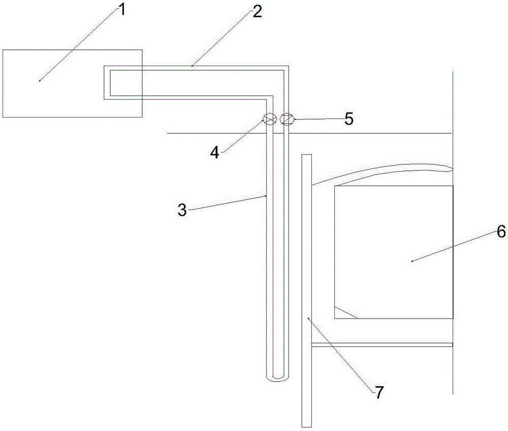
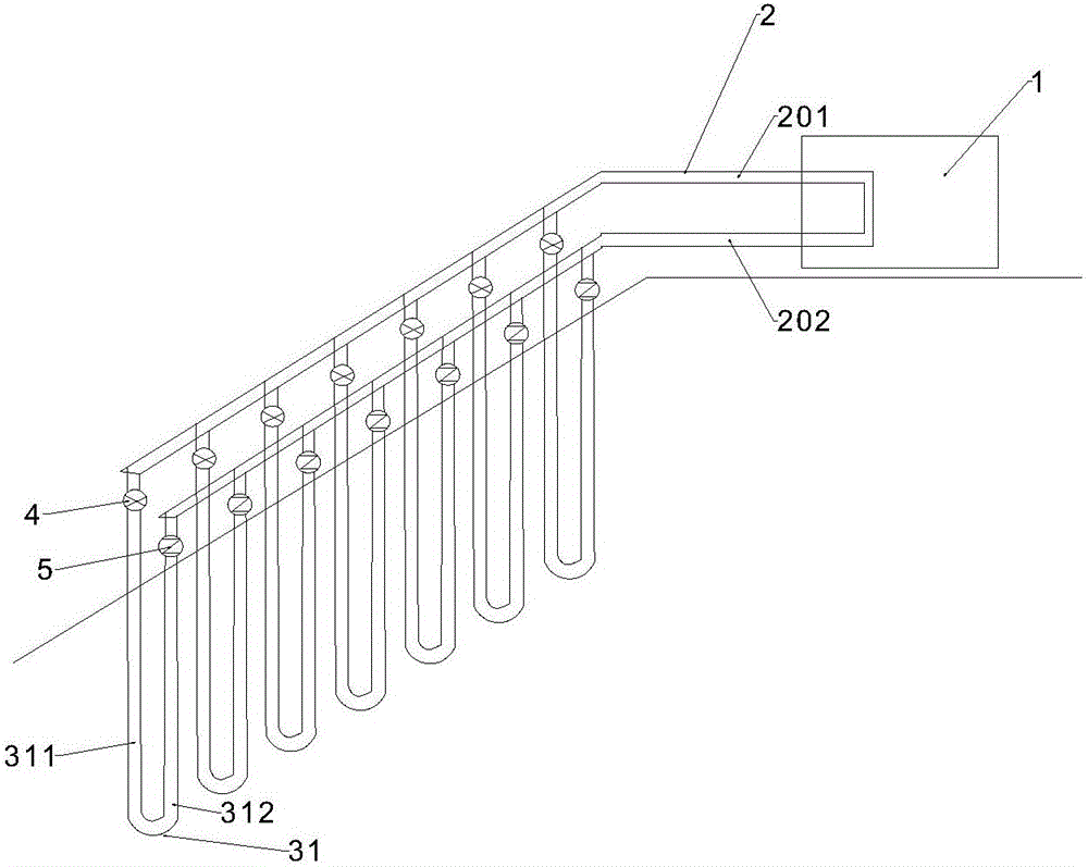
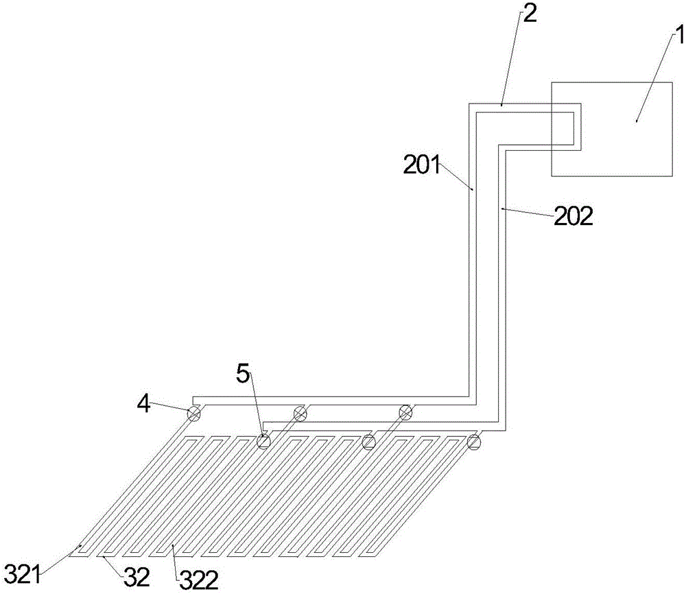
[0021] figure 1 It is a system sectional view of heating the soil around the underground low-temperature storage tank provided by Embodiment 1 of the present invention; figure 2 It is a schematic diagram of the buried pipe structure around the underground cryogenic storage tank provided in Embodiment 1 of the present invention; image 3 It is a schematic diagram of the buried pipe structure at the bottom of the underground low-temperature storage tank provided in Embodiment 1 of the present invention; as shown in the figure, the system for heating the soil around the underground low-temperature storage tank provided by the present invention includes: The buried pipe 3 for soil heating, the ground source heat pump air conditioner 1 for exchanging heat between the water circulating in the buried pipe 3 and the external environment, and the connecting main pipe 2 connecting the buried pipe 3 and the ground source heat pump air conditioner 1; the buried pipe 3 is arranged around...


PUM


Abstract

The invention discloses a system for heating soil bodies around an underground cryogenic storage tank and belongs to the technical field of soil heating. The system comprises buried pipes, a ground-source heat pump air conditioner and a connecting header pipe, wherein the buried pipes are used for heating the soil bodies around the underground cryogenic storage tank, the ground-source heat pump air conditioner is used for exchanging heat between water circulating in the buried pipes and an external environment, and the connecting header pipe is used for connecting the buried pipes with the ground-source heat pump air conditioner. The buried pipes are arranged on the periphery and the bottom of the underground cryogenic storage tank. A closed circulating system is formed by the buried pipes and the connecting header pipe. During operation of the system, circulating water enters the buried pipes through the connecting header pipe for heat exchanging with the soil bodies around the underground cryogenic storage tank, the temperature of the soil bodies rises, and the temperature of the water is lowered. Cryogenic water penetrates through the ground-source heat pump air conditioner through the connecting header pipe again, heat exchange is conducted between the cryogenic water and the environment around the ground-source heat pump air conditioner, the temperature of the water rises, and the environment temperature is lowered. The heated water reenters the buried pipes through the connecting header pipe, the circulating system is formed, the soil bodies around the underground cryogenic storage tank are heated, and refrigeration of the ground-source heat pump air conditioner is facilitated.

Description

technical field [0001] The invention relates to the technical field of soil heating, in particular to a system for heating soil around an underground low-temperature storage tank. Background technique [0002] With the acceleration of the urbanization process and the continuous growth of the population, the amount of energy required for urban construction and development is also increasing, and the demand for energy storage equipment is also increasing. Due to the shortage of urban land resources, underground cryogenic storage tanks are playing an increasingly important role in the field of energy storage. [0003] The working environment of underground cryogenic storage tanks for liquefied natural gas and other energy sources is often a harsh environment of low temperature and high pressure. For example, to store liquefied natural gas, it must be stored in an environment of more than minus 160 degrees Celsius. Because the medium around the underground cryogenic storage tan...

Claims


Application Information

Patent Timeline
Patent Type & Authority Applications(China)
IPC IPC(8): F25B30/06F24F5/00
CPCY02B10/40F25B30/06F24F5/0046F24F2005/0057
Inventor 夏才初张计锋杜时贵安康
Owner SHAOXING UNIVERSITY
Why Eureka
Try Eureka