Solution defrosting and freezing regenerated air source heat pump unit

A technology for regenerating air and solution regeneration, which is applied in the fields of air conditioners, heat pumps, and refrigeration. It can solve the problem of energy loss in defrosting of heat pump units that cannot effectively realize frost-free operation of heat pump units, difficulty in meeting the heat required for solution regeneration, and difficulty in achieving solution regeneration. Temperature requirements and other issues to achieve the effect of improving convenience and flexibility, avoiding energy loss, and solving difficult regeneration

Inactive Publication Date: 2016-12-07
NANJING UNIV OF SCI & TECH
View PDF7 Cites 11 Cited by
  • Summary
  • Abstract
  • Description
  • Claims
  • Application Information

AI Technical Summary

Problems solved by technology

Although this method can greatly reduce the volume of the system, because the condensation temperature of the heat pump system is relatively low, it is difficult to meet the regeneration temperature requirements of the solution, and the heat obtained by the supercooling of the refrigerant is less, and it is difficult to meet the requirements for solution regeneration. heat
To sum up, none of the current frost-free air source heat pump technologies can effectively realize the frost-free operation of the heat pump unit and reduce the defrosting energy loss of the heat pump unit, and the method of dehumidifying the inlet air to suppress frosting will cause Reduce the heat transfer performance of the outdoor heat exchanger and the heating performance of the heat pump unit

Method used


Image

  • Solution defrosting and freezing regenerated air source heat pump unit
  • Solution defrosting and freezing regenerated air source heat pump unit
  • Solution defrosting and freezing regenerated air source heat pump unit

Examples


Embodiment 1

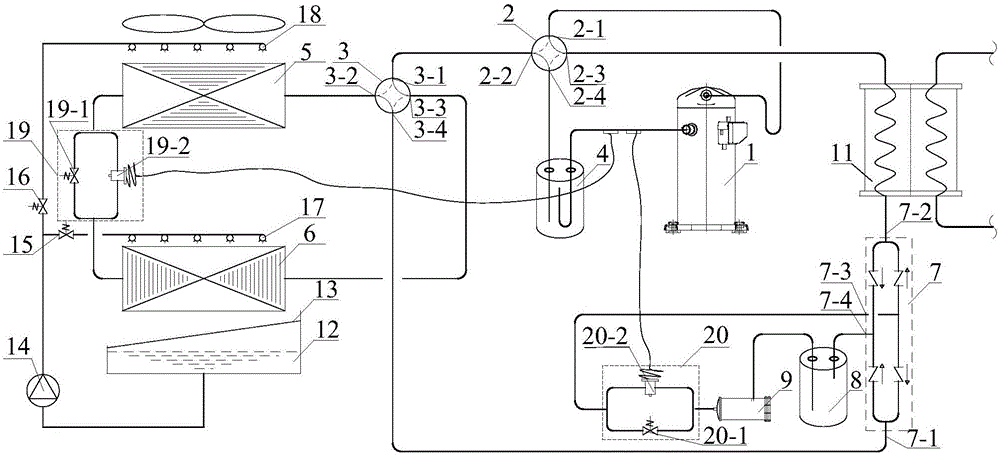
[0020] combine figure 1 , the solution defrosting freezing regeneration air source heat pump unit of the present invention uses the low-temperature refrigerant on the evaporation side to freeze and regenerate the dilute solution after defrosting, and includes a compressor 1 for inhaling gaseous refrigerant and compressing and outputting it. Connecting to reversing valve 2, gas-liquid separator 4, user-side heat exchanger 11, check valve assembly 7, high-pressure liquid reservoir 8, and dry filter 9. The second interface 7-2 of the one-way valve assembly 7 is connected to the outlet of the user-side heat exchanger 11, and the fourth interface 7-4 of the one-way valve assembly 7 is connected to the inlet of the high-pressure accumulator 8, and the high-pressure accumulator 8 is sequentially connected with the dry filter 9 and then connected with the inlet of the second throttle valve assembly 20, and the outlet of the second throttle valve assembly 20 is connected with the third...

Embodiment 2

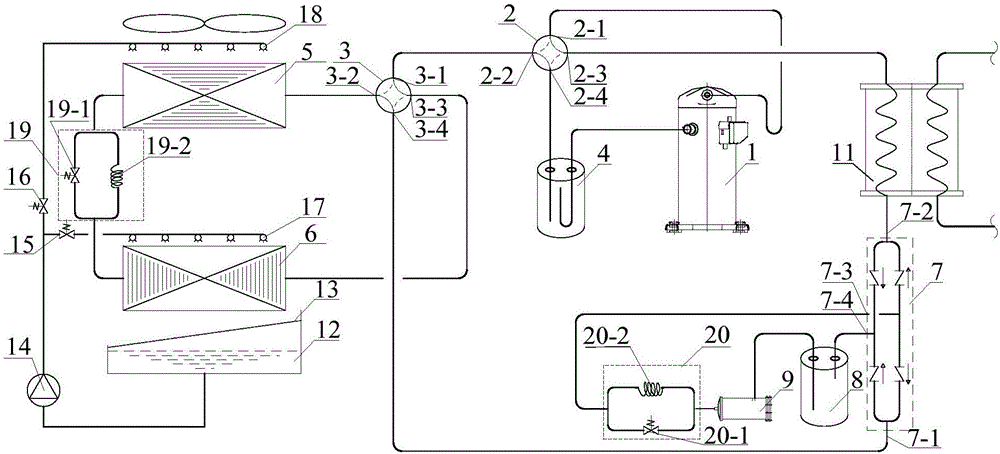
[0040] combine figure 2, the solution defrosting freezing regeneration air source heat pump unit of the present invention uses the low-temperature refrigerant on the evaporation side to freeze and regenerate the dilute solution after defrosting, and includes a compressor 1 for inhaling gaseous refrigerant and compressing and outputting it. Connecting to reversing valve 2, gas-liquid separator 4, user-side heat exchanger 11, check valve assembly 7, high-pressure liquid reservoir 8, and dry filter 9. The second interface 7-2 of the one-way valve assembly 7 is connected to the outlet of the user-side heat exchanger 11, and the fourth interface 7-4 of the one-way valve assembly 7 is connected to the inlet of the high-pressure accumulator 8, and the high-pressure accumulator 8 is sequentially connected with the dry filter 9 and then connected with the inlet of the second throttle valve assembly 20, and the outlet of the second throttle valve assembly 20 is connected with the third...

Embodiment 3

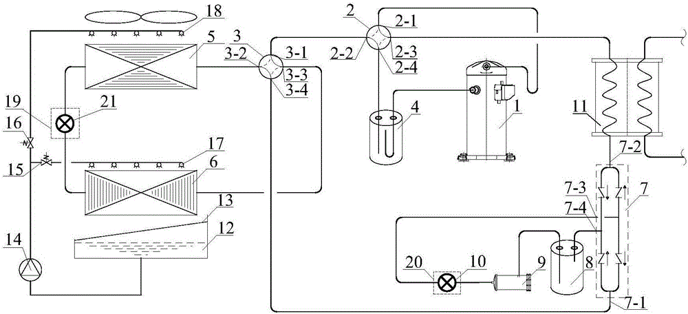
[0044] combine image 3 , the solution defrosting freezing regeneration air source heat pump unit of the present invention uses the low-temperature refrigerant on the evaporation side to freeze and regenerate the dilute solution after defrosting, and includes a compressor 1 for inhaling gaseous refrigerant and compressing and outputting it. Connecting to reversing valve 2, gas-liquid separator 4, user-side heat exchanger 11, check valve assembly 7, high-pressure liquid reservoir 8, and dry filter 9. The second interface 7-2 of the one-way valve assembly 7 is connected to the outlet of the user-side heat exchanger 11, and the fourth interface 7-4 of the one-way valve assembly 7 is connected to the inlet of the high-pressure accumulator 8, and the high-pressure accumulator 8 is sequentially connected with the dry filter 9 and then connected with the inlet of the second throttle valve assembly 20, and the outlet of the second throttle valve assembly 20 is connected with the third...


PUM


Abstract

The invention discloses a solution defrosting and freezing regenerated air source heat pump unit. The solution defrosting and freezing regenerated air source heat pump unit comprises a compressor, a first four-way reversing valve, a gas-liquid separator, a user side heat exchanger, a one-way valve assembly, a second four-way reversing valve, a solution regeneration heat exchanger, an outdoor heat exchanger and a first throttle valve assembly. The one-way valve assembly is connected with the user side heat exchanger, a high-pressure liquid reservoir, the second four-way reversing valve and a second throttle valve assembly. A dry filter is connected between a liquid outlet of the high-pressure liquid reservoir and the second throttle valve assembly. The second four-way reversing valve is further connected with the first four-way reversing valve, the outdoor heat exchanger and the solution regeneration heat exchanger. The first throttle valve assembly is connected between the solution regeneration heat exchanger and the outdoor heat exchanger. Zero-energy-consumption defrosting of a solution to the air source heat pump unit is achieved, and no halt is needed in the defrosting process; and the defrosted dilute solution is regenerated in a freezing regeneration manner, and the heating performance and defrosting reliability and high efficiency of the heat pump unit are effectively improved.

Description

technical field [0001] The invention belongs to the technical field of refrigeration, air conditioning and heat pumps, in particular to a solution defrosting freezing regeneration air source heat pump unit. Background technique [0002] In the middle and lower reaches of the Yangtze River in my country and similar climate regions, the outdoor air temperature and humidity parameters in winter are often in the frosting area of ​​the air source heat pump. In this area, the air source heat pump is used for heating operation in winter. When the air dew point temperature is lower than the freezing point temperature of water, frost will appear on the surface of the outdoor heat exchanger. When the surface of the outdoor heat exchanger of the unit is frosted, the heat transfer resistance of the outdoor heat exchanger will increase, the area of ​​the air circulation channel will decrease, and the ventilation volume of the outdoor heat exchanger will decrease, which will eventually lea...

Claims


Application Information

Patent Timeline
Patent Type & Authority Applications(China)
IPC IPC(8): F25B47/02
CPCY02B30/52F25B47/027
Inventor 余延顺曹琳
Owner NANJING UNIV OF SCI & TECH
Why Eureka
Try Eureka