Multi-cold pipe vertical efficient condenser

A condenser and cold tube technology, which is applied in the field of multi-cold tube vertical high-efficiency condensers, can solve the problem that the heat exchange efficiency of the condenser is not very high, and achieve the effects of improving the efficiency, improving the outflow efficiency, and increasing the contact area.

Pending Publication Date: 2016-12-07
成都馨迪璐莎科技有限公司
View PDF0 Cites 0 Cited by
  • Summary
  • Abstract
  • Description
  • Claims
  • Application Information

AI Technical Summary

Problems solved by technology

The heat exchange efficiency of the condenser in the prior art is not very high, in order to meet the production requirements, a condenser with better heat exchange efficiency is needed to solve the above problems

Method used


Image

  • Multi-cold pipe vertical efficient condenser
  • Multi-cold pipe vertical efficient condenser
  • Multi-cold pipe vertical efficient condenser

Examples


Embodiment 1

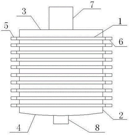
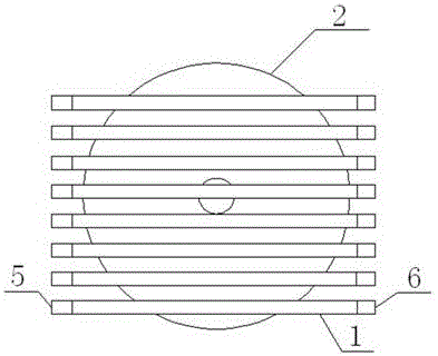
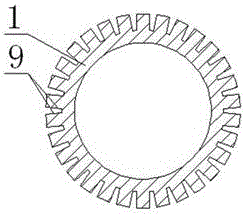
[0020] A multi-cooling tube vertical high-efficiency condenser has the advantages of high heat exchange efficiency, such as figure 1 , image 3 As shown, it is specially set to the following structure: comprising a closed cylindrical barrel body and a plurality of cold pipes 1 inserted in the barrel body; The top plate 3 at the top and the bottom plate 4 connected to the bottom of the side wall plate 2, the middle part of the cold pipe 1 is arranged through the side wall plate 2, and the two ends of the cold pipe 1 are arranged on the outside of the side wall plate 2 and respectively enter the cooling liquid. The liquid pipe 5 is connected with the cooling liquid outlet pipe 6; the top of the top plate 3 is connected with a hot gas intake pipe 7, and the bottom of the bottom plate 4 is connected with a condensed water outlet pipe 8; the outer wall of the cold pipe 1 is along its axis direction. There are a plurality of grooves 9; a protrusion is formed between the grooves 9 o...

Embodiment 2

[0022] This embodiment is further optimized on the basis of the above-mentioned embodiment, and further to better realize the present invention, such as figure 1 As shown, the following arrangement is particularly adopted: the bottom plate 4 is a circular arc-shaped disc with upward bending around it, which can conveniently collect the condensed water and make the condensed water slide smoothly to the middle of the bottom plate 4 .

Embodiment 3

[0024] This embodiment is further optimized on the basis of any of the above-mentioned embodiments, and further to better realize the present invention, such as figure 1 As shown, the following arrangement is particularly adopted: the middle part of the bottom plate 4 is communicated with the condensate water outlet pipe 8, so that the condensed water accumulated in the middle part can flow out to the outside through the condensate water outlet pipe 8.


PUM


Abstract

The invention discloses a multi-cold pipe vertical efficient condenser. The multi-cold pipe vertical efficient condenser comprises a closed cylindrical barrel body, and multiple cold pipes inserted in the barrel body; the barrel body includes a side wall plate vertically placed, a top plate connected to the top of the side wall plate, and a baseplate connected to the bottom of the side wall plate; the middle parts of the cold pipes are inserted in the side wall plate; two ends of the cold pipes are arranged on the outer side of the side wall plate, and are respectively connected with cooling liquid inlet pipes and cooling liquid outlet pipes; the top of the top plate is communicated with a hot air intake pipe; the bottom of the baseplate is communicated with a condensed water outlet pipe; multiple grooves are formed in the axle directions of the outer walls of the cold pipes; the baseplate is an arc disc with upwards bent periphery; the middle part of the baseplate is communicated with the condensed water outlet pipe; and the cold pipes are uniformly distributed on the horizontal surface and the vertical surface in the barrel body. Compared with the prior art, the multi-cold pipe vertical efficient condenser has the advantage of high heat exchange efficiency.

Description

technical field [0001] The invention relates to the field of condensation equipment, in particular to a multi-cooling tube vertical high-efficiency condenser. Background technique [0002] The condenser is a part of the refrigeration system and belongs to a type of heat exchanger, which can convert gas or vapor into liquid, and transfer the heat in it to the air near the tube in a fast way; the working process of the condenser is a Exothermic process, so the condenser temperature is higher. [0003] Power plants use many condensers to condense the steam from the turbines. Condensers are used in refrigeration plants to condense refrigeration vapors such as ammonia and freons. Condensers are used in the petrochemical industry to condense hydrocarbons and other chemical vapors. During distillation, the device that converts vapor into liquid is also called a condenser. All condensers operate by removing heat from the gas or vapor. The heat exchange efficiency of the condens...

Claims


Application Information

Patent Timeline
Patent Type & Authority Applications(China)
IPC IPC(8): F28B1/02F25B39/04
Inventor 王志国
Owner 成都馨迪璐莎科技有限公司
Why Eureka
Try Eureka