Projector calibration method based on red and blue checkerboard calibration plate

A technology for calibrating plates and projectors, which is applied to instruments, measuring devices, optical devices, etc., can solve the problems of low measurement efficiency, no obvious inhibition of phase error, unavoidable phase error, etc., to achieve uniform reflectivity, improve Phase unwrapping accuracy, the effect of reducing the effects of gamma nonlinearity and ambient noise

Active Publication Date: 2016-12-07
TAIYUAN UNIVERSITY OF SCIENCE AND TECHNOLOGY
View PDF6 Cites 21 Cited by
  • Summary
  • Abstract
  • Description
  • Claims
  • Application Information

AI Technical Summary

Problems solved by technology

[0003] In actual measurement, the deformed grating fringe image collected by the camera will be affected by factors such as projector-camera gamma nonlinearity and environmental noise, so the phase error will inevitably be introduced
In order to reduce the impact of environmental noise and gamma nonlinear factors on the measurement accuracy of the system, Zhang et al. assumed that the main source of the phase error is the gamma nonlinearity of the projector, and used the look-up table method to increase the phase accuracy by 5.6 times. Good suppression of errors caused by gamma nonlinearity of the projector, but no significant suppression of phase errors caused by ambient noise
Zhou et al. established a model of the relationship between ambient light and phase error, so that the phase error was significantly red

Method used


Image

  • Projector calibration method based on red and blue checkerboard calibration plate
  • Projector calibration method based on red and blue checkerboard calibration plate
  • Projector calibration method based on red and blue checkerboard calibration plate

Examples


Embodiment Construction

[0068] In order to describe the technical content of the present invention more clearly, further detailed description will be given below in conjunction with specific embodiments.

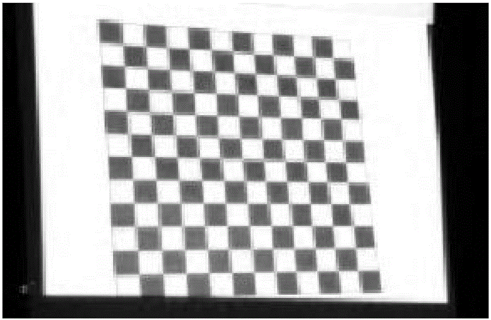
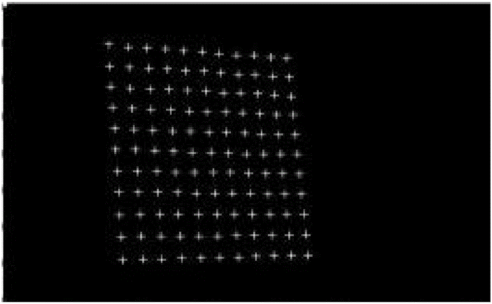
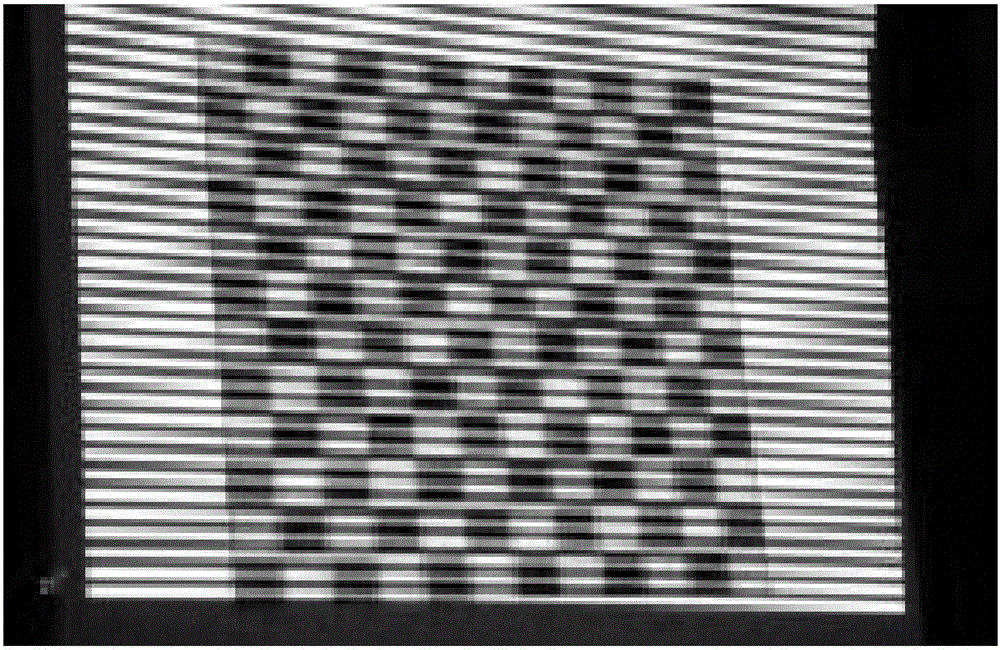
[0069] The calibration principle of the projector calibration method based on the red and blue checkerboard calibration board of the present invention is as follows: the projector is regarded as a reverse camera, and the camera calibration method can be used to calibrate the parameters of the projector. Specifically: the projector projects the vertical and horizontal white sinusoidal phase shift grating stripe images generated by computer software to the plane of the red and blue checkerboard calibration plate, and the camera at a certain angle with the projector acquires the deformed grating stripe images, and Calculate the unwrapped phase in the vertical and horizontal directions separately. Determine the pixel coordinates of the corner points in the projection image according to the unfolded pha...


PUM


Abstract

The invention relates to a projector calibration method based on a red and blue checkerboard calibration plate. The method comprises the steps that the calibration plate is selected; a measurement system is set up; a corner point coordinate is extracted; deformation grating fringe images are collected; a filtering function is constructed for compensation, wherein Fourier transforming is carried out on the acquired deformation grating fringe images in horizontal and vertical directions to acquire the amplitude spectrum image of deformation grating stripes; a frequency domain filtering function is constructed for filtering to extract fundamental frequency component and direct current component in the amplitude spectrum image; inverse Fourier transforming is carried out on the extracted fundamental frequency component and direct current component to acquire compensated deformation grating fringe images in horizontal and vertical directions; the wrapped phase images of the compensated deformation grating fringe images in horizontal and vertical directions are calculated; a target image is acquired after dephasing; and a projector is calibrated. According to the invention, the constructed frequency domain filtering function can filter out components except the fundamental frequency component and the direct current component; and the influence of gamma nonlinearity and environmental noise can be obviously reduced.

Description

technical field [0001] The invention relates to a projector calibration method, in particular to a projector calibration method with a plane calibration plate with uniform reflectivity, and in particular to a projector calibration method based on a red and blue checkerboard calibration plate. Background technique [0002] In phase measurement profilometry, the calibration of the hardware system is a necessary step to complete the transformation from the pixel coordinates of the image plane and the projection plane to the three-dimensional coordinates of the space, and the calibration accuracy determines the measurement accuracy of the system. Hardware system calibration includes internal and external parameter matrix calibration of cameras and projectors. At present, camera calibration methods are becoming more and more mature. A typical example is the Matlab camera calibration toolbox established by Bouguet et al. Since the second-order radial and tangential distortion of th...

Claims


Application Information

Patent Timeline
IPC IPC(8): G01B11/25
CPCG01B11/2504
Inventor 赵贤凌张华煜郑晓华田继红白墅洁刘建生
Owner TAIYUAN UNIVERSITY OF SCIENCE AND TECHNOLOGY
Why Eureka
Try Eureka