
Displacement and movement time synchronous calibration method and device

A technology for calibrating devices and moving time, applied in the direction of instruments, etc., can solve the problems of synchronous calibration, poor applicability, high cost, etc., achieve accurate calibration results, good applicability, and achieve the effect of calibration

Active Publication Date: 2016-12-07
RES INST OF HIGHWAY MINIST OF TRANSPORT
View PDF6 Cites 3 Cited by
  • Summary
  • Abstract
  • Description
  • Claims
  • Application Information

AI Technical Summary

Problems solved by technology

The cost of displacement calibration with high-precision grating scale or laser interferometer is high
[0011] 2) Synchronous calibration of displacement and time cannot be performed
The existing technology can only calibrate the displacement detection function and the timing function separately, but cannot calibrate the synchronization of the displacement detection function and the timing function, which increases the difficulty of calibration and cannot guarantee the accuracy of the calibration
[0012] 3) poor applicability

Method used


Image

  • Displacement and movement time synchronous calibration method and device
  • Displacement and movement time synchronous calibration method and device
  • Displacement and movement time synchronous calibration method and device

Examples


example 1

[0062] Example 1 hardware connection schematic diagram and flow chart

[0063] The present invention can be used for calibrating the penetration of asphalt penetration meter, and its flow chart is as follows:

[0064] refer to Figure 6 The flow chart of Example 1 is shown, and the implementation process of the technical solution of Example 1 is as follows:

[0065] (1) Rotate the calibration device 90° and place it.

[0066] (2) The calibration device performs a self-test upon power-on.

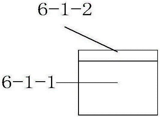
[0067] (3) Install the follower module 1 on the calibration device, and connect the data cable of the follower module to the host.

[0068] (4) Adjust the asphalt penetrometer so that the bottom end of the needle is in vertical contact with the upper part of the following module 1 (ie, the upper surface of the pressure detector).

[0069] (5) Start the calibration work of the calibration device.

[0070] (6) Start the asphalt penetrometer, and the asphalt penetrometer starts to work.

...

example 2

[0081] 1) hardware connection diagram and technical flow chart of implementation example 2

[0082] The present invention can be used for calibrating bridge deflection meter calibrating device, and its flow chart is as follows Figure 7 Shown:

[0083] 2) In combination with the above drawings, describe the detailed implementation process of the technical solution of Embodiment 2.

[0084] Example 2 technical solution implementation process is as follows:

[0085] (1) Place the device rotated 90°.

[0086] (2) The device self-checks when it is powered on.

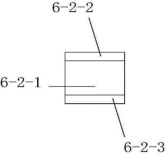
[0087] (3) Install the follower module 3 on the calibration device, and connect the data cable of the follower module to the host.

[0088] (4) Adjust the connecting piece of the following module 3, and adjust the distance between the two pressure detectors of the following module 3, so that the slider of the bridge deflection meter calibration device is embedded in the groove of the following module 3, and the two are ...


PUM


Abstract

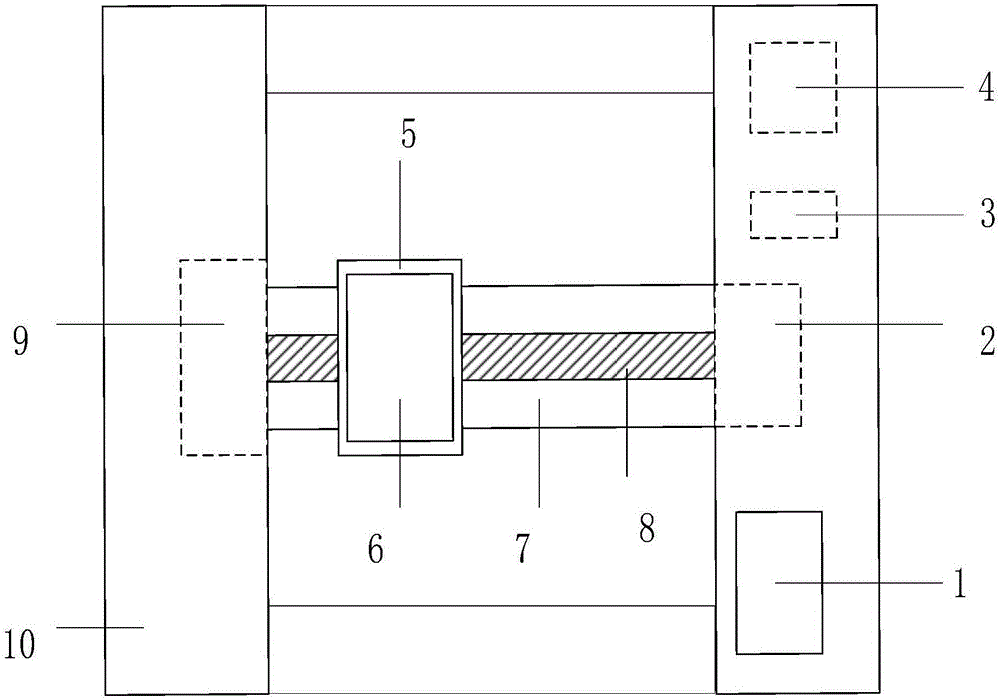
The invention discloses a displacement and movement time synchronous calibration method and device, and belongs to the field of road, bridge and tunnel building construction. The device is characterized by comprising a displayer, a motor, a motor driver, a host, a sliding table, following modules, a sliding rail, a lead screw, a rotary encoder and a support; the following modules are fixed to the sliding table, the sliding table is placed on the lead screw, the lead screw is arranged on the sliding rail, the rotary encoder is arranged at one end of the lead screw, and the motor is arranged at the other end of the lead screw; the sliding rail is arranged on the support; the host is connected with the following modules, the motor driver, the rotary encoder and the displayer. Synchronous calibration of displacement and movement time is achieved, accuracy of the calibration result is guaranteed, and high applicability is achieved.

Description

technical field [0001] A displacement and movement time synchronization calibration method and device belong to the field of road, bridge and tunnel construction. Background technique [0002] With the rapid development of China's economy, the construction volume of roads, bridges and tunnels is increasing day by day, and the types of road and bridge engineering testing equipment are also increasing, so there is a huge demand for equipment calibration. During the calibration of road and bridge engineering testing equipment, it was found that many equipment need to calibrate displacement and moving time, such as asphalt penetration meter, bridge deflection meter calibration device, asphalt softening point meter, etc. At present, the existing calibration methods do not have a unified method for calibrating displacement and moving time, and generally have problems such as poor applicability, high cost, difficulty in traceability, and low accuracy. Therefore, it is necessary to ...

Claims


Application Information

Patent Timeline
IPC IPC(8): G01D18/00
CPCG01D18/00
Inventor 何华阳周毅姝郭鸿博陈柳清张金凝冷正威
Owner RES INST OF HIGHWAY MINIST OF TRANSPORT
Learn More