
Bridge detection method and detection system based on vehicle-bridge coupling vibration analysis

A technology for vibration analysis and bridge detection, which is used in elastic testing, machine/structural component testing, measuring devices, etc., and can solve problems such as limited application, accumulation of errors, and low accuracy.

Active Publication Date: 2016-12-07
SOUTHEAST UNIV
View PDF5 Cites 35 Cited by
  • Summary
  • Abstract
  • Description
  • Claims
  • Application Information

AI Technical Summary

Problems solved by technology

However, these methods also have problems. The second integration of the acceleration signal will lead to error accumulation and low accuracy; the curvature inversion method based on the FBG strain sensor will be affected by stress concentration and axial stress in the real bridge test
[0005] Environmental vibration testing is the main means of existing health monitoring. It directly uses natural conditions such as wind load and traffic flow to excite bridges. Compared with artificial vibration testing, it has the advantage of convenient operation. : frequency, damping and mode shape etc.
The impact vibration test measures the time history of the input impact force and the output structure response of the structure, and can obtain more detailed structural parameters. However, due to the need to close the traffic during the test, it needs to have the disadvantages of an excitation device with a sufficiently large impact force amplitude and broadband characteristics. Limits its wide application in engineering practice

Method used


Image

  • Bridge detection method and detection system based on vehicle-bridge coupling vibration analysis
  • Bridge detection method and detection system based on vehicle-bridge coupling vibration analysis
  • Bridge detection method and detection system based on vehicle-bridge coupling vibration analysis

Examples


Embodiment

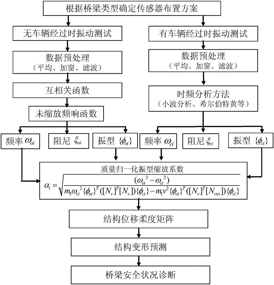
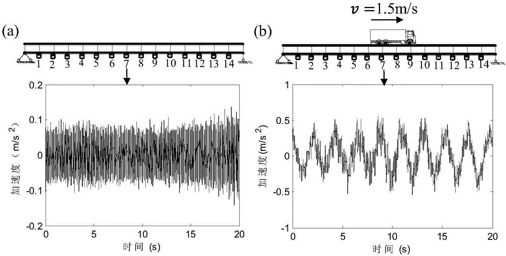
[0073] In the following, a typical simply supported girder bridge is used to illustrate the implementation steps of the proposed identification of the displacement compliance matrix of the bridge structure based on the bridge vibration response with or without vehicles passing by. A typical bridge such as figure 2 As shown, the span of the bridge is 30m, the bridge is divided into 15 units, each unit length is 2m, the distance between adjacent acceleration sensors can be determined to be 2m, and a total of 14 sensors are arranged. The specific steps are as follows:

[0074] Step 1: First, determine the arrangement of sensors according to the characteristics of the bridge. In this implementation case, 14 acceleration sensors (such as figure 2 It is worth noting that in the actual test of the bridge, the bridge deck has vehicles passing by, so the acceleration sensor should be arranged on the side of the bridge deck or inside the box girder.

[0075] Step 2: Collect the vib...


PUM


Abstract

The invention discloses a bridge detection method and detection system based on vehicle-bridge coupling vibration analysis. The bridge detection method comprises the following steps: obtaining time-variant model parameters and time-invariant model parameters of having or not having vehicle passing through a group of sensors which are arranged on a bridge in the length direction; computing mass-normalized mode coefficients at moments of a bridge structure; resolving an average value of zoom coefficients at all moments; obtaining a mass-normalized mode of the structure; reconstructing a frequency-function matrix of the structure; conducting displacement flexibility identification. According to the invention, the bridge detection method addresses the inconvenience of on-site detection and poor precision of current flexibility detection devices, overcomes the inability of environment vibration to identify deep parameters of the structure and the high difficulty of impact vibration on-site detection. The detection method not only can obtain static deformation of the structure, and can obtain rigidity information of the structure, thus providing effective evaluation of the safety of the bridge structure.

Description

technical field [0001] The invention relates to a method for calculating the mass normalized mode shape of a structure and identifying the displacement compliance of the structure based on the vibration response of the bridge with or without vehicles passing by, which can realize the deflection prediction and safety state evaluation of the bridge. Background technique [0002] With the maturity of prestressing technology and steel bridge technology, a large number of major infrastructures such as long-span bridge structures, high-rise building structures, and large-span space structures have been completed or are under construction. For example, Japan built Akashi-akyo with a span of 1990m Suspension bridge, the United States built the famous Chesapeake Bay Bridge, and our country completed the Sutong Yangtze River Bridge opened to traffic in 2008. This bridge created the world's four largest main span, deepest foundation, highest bridge tower, and longest cable at that time....

Claims


Application Information

Patent Timeline
IPC IPC(8): G01M5/00
CPCG01M5/0066
Inventor 张建田永丁程玉瑶
Owner SOUTHEAST UNIV
Learn More