Gas analysis device and method based on spectrum technology

A technology of gas analysis and spectral technology, which is applied in the direction of spectrometry/spectrophotometry/monochromator, material analysis and material analysis through optical means, and can solve the problem of poor beam collimation effect and optical interference noise suppression ability Aberration, aberration and other problems, to achieve the effect of easy realization, improved collimation effect and small size

Active Publication Date: 2016-12-07
HESAI TECH CO LTD
View PDF9 Cites 0 Cited by
  • Summary
  • Abstract
  • Description
  • Claims
  • Application Information

AI Technical Summary

Problems solved by technology

When the angle between the lens axis and the optical axis is small, the ability to suppress optical interference noise is poor; when the angle between the lens and the optical axis is large, there will be serious aberrations, and the beam collimation effect will be poor

Method used


Image

  • Gas analysis device and method based on spectrum technology
  • Gas analysis device and method based on spectrum technology
  • Gas analysis device and method based on spectrum technology

Examples


Embodiment 1

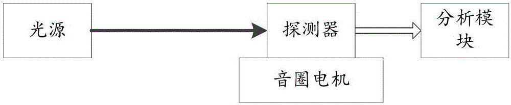
[0058] figure 1 Schematically provides a simplified structural diagram of the gas analysis device based on spectroscopic technology in this embodiment, as figure 1 As shown, the gas analysis device includes:

[0059] A light source, such as a semiconductor laser, which emits measurement light that matches the gas to be measured, such as the wavelength of the measurement light corresponding to the characteristic spectral line of the gas;

[0060] a detector, the detector converts the measurement light after interacting with the gas to be measured into an electrical signal, and transmits it to the analysis module;

[0061] A voice coil motor, the detector is fixed on the voice coil motor, and moves back and forth on the optical path, thereby adjusting the distance between the light source and the detector;

[0062] An analysis module. The analysis module processes the electrical signal using spectral techniques such as absorption spectroscopy, so as to obtain the information o...

Embodiment 2

[0069] A schematic structural diagram of a gas analysis device based on spectral technology in this embodiment, the gas analysis device includes:

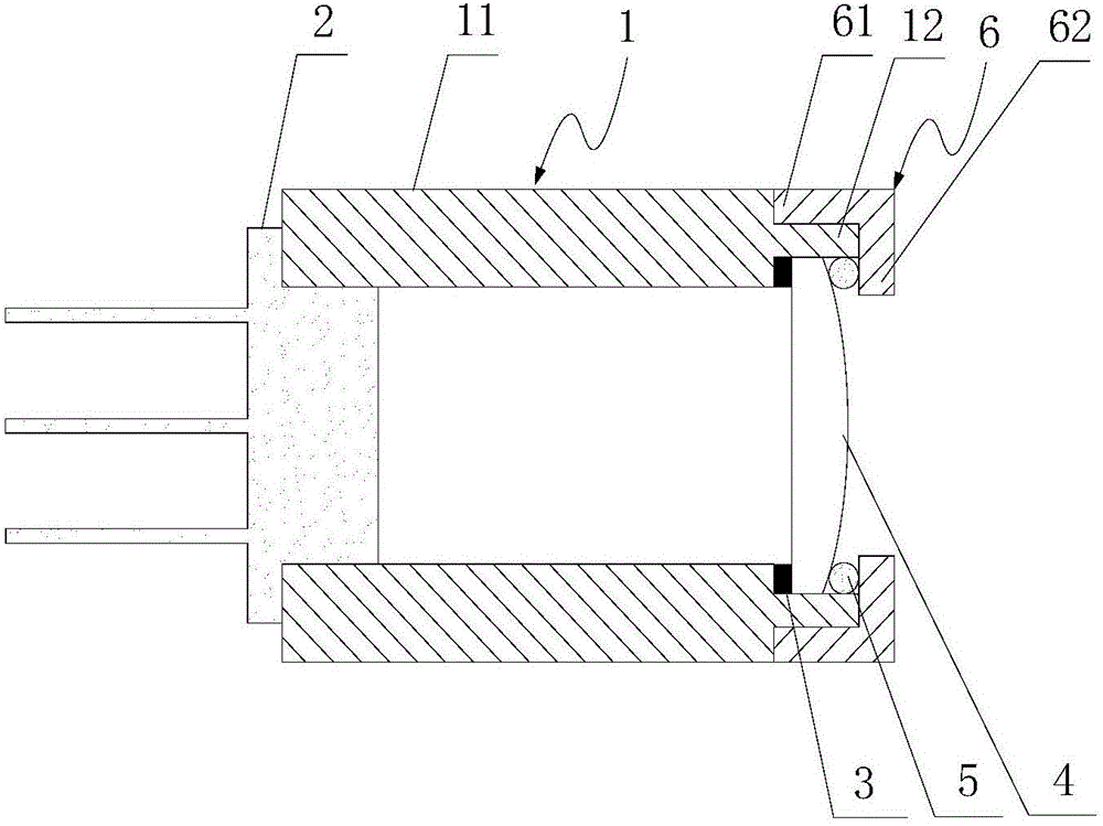
[0070] light source, figure 2 Schematically provides a simplified structural diagram of the light source of this embodiment, as figure 2 As shown, the light source includes:

[0071] Illuminant 2, such as a laser for emitting monochromatic light, said illuminant is fixed on a bracket;

[0072] Bracket 1, such as a circular sleeve, the bracket is used to carry the illuminant, and the bracket is formed with an optical channel suitable for the passage of the emitted light of the illuminant;

[0073] The fixing part 6 is, for example, a circular sleeve with a radial part at one end, the fixing part is arranged on the bracket, and is suitable for passing the outgoing light; the fixing part and the bracket are screwed together to realize detachability;

[0074] A light collimating device 4, such as a convex lens, the light collimati...

Embodiment 3

[0089] The structural diagram of the gas analysis device based on spectral technology of the present embodiment is different from Embodiment 2 in that:

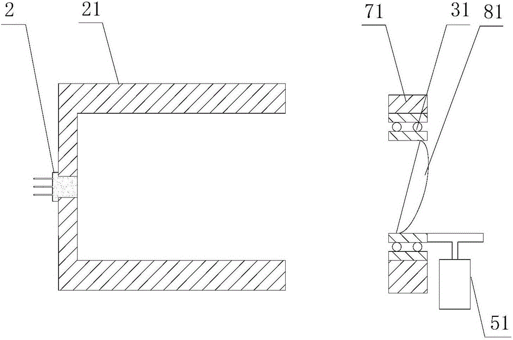
[0090] 1. If image 3 As shown, light sources include:

[0091] The luminous body 2 is used to emit monochromatic light; the luminous body is fixed on the first bracket;

[0092] The first bracket 21, such as a circular sleeve, a mounting plate, etc., the bracket is used to carry the illuminant, and the bracket is formed with an optical channel suitable for the passage of the emitted light of the illuminant;

[0093] Light collimating device 81, such as plano-convex lens, described light collimating device is fixed on the optical path of the outgoing light of described illuminant, collimates described outgoing light; The axis of described light collimating device and described outgoing light The angle between the optical axes is an acute angle, such as 2 degrees, 10 degrees, 25 degrees, etc., but not more than 30 degrees; ...


PUM


Abstract

The invention provides a gas analysis device and method based on the spectrum technology. The gas analysis device comprises a light source, a detector, a voice coil motor and an analysis module, wherein the light source emits measurement light matched with to-be-detected gas; the detector converts measurement light interacting with the to-be-detected gas into electric signals and transmits the electric signals to the analysis module; the detector is fixed to the voice coil motor and moves back and forth on a light path; the analysis module processes the electric signals through the spectrum technology, and accordingly information of the to-be-detected gas is obtained. The device has the advantages of being high in precision, simple in structure, low in cost and the like.

Description

technical field [0001] The invention relates to photoelectric analysis, in particular to a gas analysis device and method based on spectral technology. Background technique [0002] In gas sensors, the output light from diode lasers is highly divergent, requiring the use of collimating optics, such as collimating lenses. The introduction of the collimating lens will cause interference between the laser and the lens: the laser emitted by the laser and incident vertically on the rear surface of the lens will be partially reflected back to the laser, reflected at the front window of the laser, and then perpendicularly incident on the rear surface of the lens again. The outgoing light twice before and after will form an interference. In the process of measuring gas absorption signals, the fringes formed by interference will greatly reduce the gas detection limit, so it needs to be avoided or eliminated as much as possible. [0003] Traditional methods to eliminate optical inte...

Claims


Application Information

Patent Timeline
Patent Type & Authority Applications(China)
IPC IPC(8): G01N21/39G01N21/31G01J3/42G01J3/10
CPCG01J3/10G01J3/42G01N21/31G01N21/39G01J2003/423G01N2021/399Y02A50/20
Inventor 李娜陶俊向少卿孙文婷李一帆
Owner HESAI TECH CO LTD
Why Eureka
Try Eureka