Compressed air energy seismic source apparatus for seismic exploration in waters

A technology of compressed air source and seismic exploration, which is applied to seismology, seismology, and measuring devices in areas covered by water. It can solve the problems of small force on the impact cylinder, non-replaceable material, and complex structure. Achieve the effect of ensuring impact reliability, convenient operation and maintenance, and strong penetration ability

Active Publication Date: 2016-12-07
广东省地质物探工程勘察院
View PDF8 Cites 9 Cited by
  • Summary
  • Abstract
  • Description
  • Claims
  • Application Information

AI Technical Summary

Problems solved by technology

[0006] 1. The main component of the vibration source device is the air hammer. The air hammer has a small output force and low excitation energy, and cannot form an effective high-speed impact on the bottom plate of the device. Therefore, the obtained wavelet characteristics are poor, which has a negative impact on the exploration results. influences
[0007] 2. The structure used in the device to drive and control the hammer head to move up and down to hit the bottom plate is an air compressor, magnetic base plate, magnet and return spring. Controlling the up and down movement of the hammer head is difficult to achieve precise control, and it is difficult to ensure the reliability of the hammer head hitting the bottom plate
[0008] 3. The device is a boat-shaped hollow closed container. The specific gravity of the device is smaller than that of water, so it can only float on the water surface, and cannot enter the water for operation after a certain depth. The sinking depth cannot be adjusted and has no variability. The use needs to adjust the sinking depth, and vibrations of different main frequencies cannot be obtained, so the main frequency of the vibration wavelet cannot be matched, which greatly restricts the use of the device. It has limitations in the place of use and cannot fully meet the seismic exploration of water areas. requirements
[0009] 4. The vibrating plate used in this device is only made of metal material, and the material cannot be replaced, so it cannot generate vibration wavelets with different main frequencies, and cannot provide different penetration capabilities and resolution capabilities
[0010] 5. The device is packaged as a whole into a small boat, commonly known as the source boat, and the carrying body is made of metal, which is relatively heavy and expensive
[0017] At present, impact cylinders are generally used in mechanisms with sensitive reciprocating motion and little force, but have not yet appeared in the field of seismic exploration in water areas.

Method used


Image

  • Compressed air energy seismic source apparatus for seismic exploration in waters
  • Compressed air energy seismic source apparatus for seismic exploration in waters
  • Compressed air energy seismic source apparatus for seismic exploration in waters

Examples


Embodiment 1

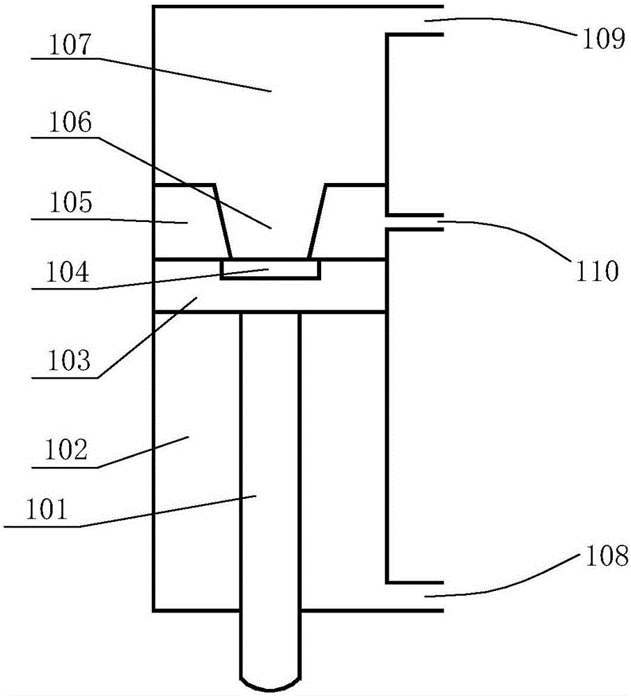
[0074] Embodiments of the present invention's compressed air source device for seismic exploration in water areas are as follows: figure 2 As shown, the barrel-type packaging structure is adopted, and the specific gravity of the device is greater than that of water. The device includes a casing 15, a compressed air source, an impact cylinder 14, a flange 6, a stainless steel bottom plate 5, a cylinder bottom backing plate 10 and a vibration plate 3.

[0075] The material of the casing 15 is stainless steel, and the casing is a single-ended vertical hollow cylinder with an open bottom and a closed top, so that the device is a barrel-shaped device as a whole, and the impact cylinder 14 is located in the casing 15. Inside, the impact cylinder 14 has two air inlets and an air outlet, the compressed air source is an air compressor, and the two air inlets are connected to the air compressor through two air inlet pipes, and the two air inlet pipes are A ports respectively. Inlet pip...

Embodiment 2

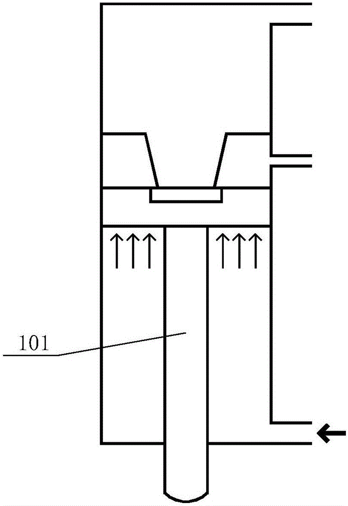
[0090] The second embodiment of the compressed air energy source device used for seismic exploration in water areas of the present invention is as follows image 3 As shown, the difference from Embodiment 1 is that this embodiment adopts a T-shaped packaging structure. The shell is a double-ended hollow cylinder with open bottom and top ends, and the top of the shell is also connected with a horizontally arranged hollow balance capsule. 22 are connected, thus forming the device as a T-shaped raft as a whole, the specific gravity of the device is less than that of water, and it can float in water. And because the device adopts an integral package structure, there is no need to worry about water ingress due to tilting of the device when it floats in water, and users can use it with confidence. The entire T-shaped raft body is made of PVC pipes, and the rest of the structure, working process and working principle are the same as those in Embodiment 1.

[0091] Example of enginee...


PUM


Abstract

The invention discloses a compressed air energy seismic source apparatus for seismic exploration in waters. The apparatus includes a housing, a compressed air source, an impact cylinder, a flange, a stainless steel base plate, a cylinder bottom pad plate and a vibration plate. The housing is a vertically arranged hollow canister body. The impact cylinder is disposed inside the housing. The flange is horizontally and fixedly installed at the bottom part of the housing. The stainless steel base plate and the vibration plate are horizontally arranged. The stainless steel plate is an annular plate having a center hole. The stainless steel plate is arranged under the flange. The vibration plate is arranged under the stainless steel base plate. The flange, the stainless steel base plate ad the vibration plate are connected through external fastening bolts which vertically penetrates. The cylinder bottom pad plate is an annular plate which is arranged between the impact cylinder and the stainless steel plate and has a center hole. An internal fastening bolt vertically penetrates the stainless steel base plate and the cylinder bottom pad plate, and then is connected to the bottom part of the impact cylinder so as to fix the impact cylinder to the stainless steel base plate in a suspension manner. The apparatus can be used in seismic exploration in waters.

Description

technical field [0001] The invention relates to geophysical exploration equipment, in particular to a compressed air source device for seismic exploration in water areas. Background technique [0002] With the development of the national economy, a large number of bridges, tunnels, and wharfs have been built in waters at home and abroad. Due to complex geological conditions, geophysical exploration is required. [0003] Offshore oil exploration and exploitation drilling platforms and their surroundings also require marine engineering geological exploration, as well as geophysical exploration. Geophysical prospecting in water areas is usually dominated by seismic prospecting. [0004] At present, the seismic sources used in water area seismic exploration include air gun sources, electric spark sources, Boomer, and source ships. The air gun seismic source has high excitation energy and strong penetrating ability, but the equipment is bulky, expensive, troublesome to operate...

Claims


Application Information

Patent Timeline
Patent Type & Authority Applications(China)
IPC IPC(8): G01V1/133G01V1/38
CPCG01V1/133G01V1/38
Inventor 李学文章哲辉马锦国伍卓鹤邓杰方程久贵
Owner 广东省地质物探工程勘察院
Why Eureka
Try Eureka