Electric spindle multi-axial fatigue life prediction method and fatigue life reliability assessment method

A technology of fatigue life prediction and fatigue life, which is applied in the direction of electrical digital data processing, special data processing applications, instruments, etc., can solve problems such as inability to respond to electric spindles, and achieve the effect of avoiding high costs

Active Publication Date: 2016-12-07
UNIV OF SCI & TECH BEIJING
View PDF5 Cites 46 Cited by
  • Summary
  • Abstract
  • Description
  • Claims
  • Application Information

AI Technical Summary

Problems solved by technology

[0006] The technical problem to be solved by the present invention is to provide a multi-axis fatigue life prediction method and a fatigue life reliability evaluation method of an electric spindle, which overcomes the defect that the single-axis fatigue life cannot reflect the actual a

Method used


Image

  • Electric spindle multi-axial fatigue life prediction method and fatigue life reliability assessment method
  • Electric spindle multi-axial fatigue life prediction method and fatigue life reliability assessment method
  • Electric spindle multi-axial fatigue life prediction method and fatigue life reliability assessment method

Examples


Embodiment approach

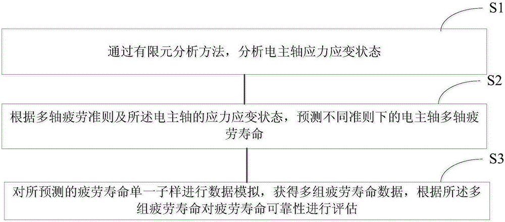
[0057] The multi-axis fatigue life prediction method of the electric spindle of the present invention comprises the following steps:

[0058] Step S1, analyzing the stress and strain state of the electric spindle by means of finite element analysis.

[0059] Before this step, it may also include: establishing a three-dimensional finite element model of the electric spindle. Specifically, based on the two-dimensional drawing of the main shaft, the electric spindle model can be established in the solidworks three-dimensional modeling software, and the structure of the model can be simplified; metamodel.

[0060] In this step, the stress-strain state of the electric spindle is analyzed, which specifically includes the following steps:

[0061] Step S101, under consideration of load conditions such as shear stress or compressive stress, torque and bearing support, perform static mechanical analysis on the electric spindle to determine the instantaneous stress and strain state of...

Embodiment

[0073] This embodiment provides a method for predicting the multi-axis fatigue life of an electric spindle and evaluating the reliability of the fatigue life. In this embodiment, the A204 turning electric spindle is taken as an example, and multi-axis fatigue life prediction and reliability analysis are carried out for this type of electric spindle. The motorized spindle and spindle described below all refer to the settings here.

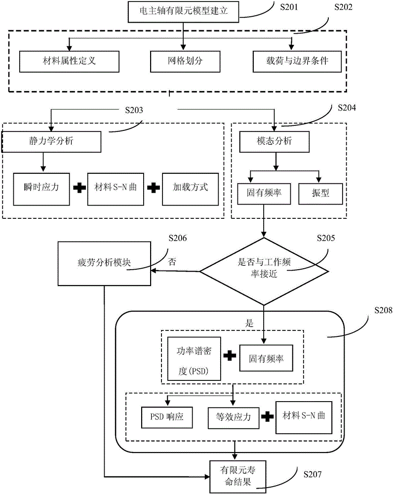
[0074] figure 2 It is a schematic diagram of the multi-axis fatigue life prediction flow chart of the electro-spindle finite element simulation of this embodiment. Such as figure 2 As shown, the multiaxial fatigue life prediction method of this embodiment includes the following steps:

[0075] Step S201, establishing a finite element model of the electric spindle.

[0076] In this step, according to the 2D CAD drawing of the motorized spindle, the 3D solid modeling of the A204 turning motorized spindle is completed in the 3D modeling software ...


PUM


Abstract

The invention provides an electric spindle multi-axial fatigue life prediction method and a fatigue life reliability assessment method, and aims to solve the problems that the single-axial fatigue life in the prior art cannot express the electric spindle practical application status; the multi-axial fatigue life prediction method comprises the following steps: using a finite element analysis method to analyze electric spindle stress strain status; predicting the electric spindle multi-axial fatigue life under different rules according to the multi-axial fatigue rules and the electric spindle stress strain status. Data simulation is carried out for a fatigue life single subsample on said basis, thus obtaining multi-group fatigue life data, and assessing the fatigue life reliability according to the multi-group fatigue life data. The method can carry out assessment and reliability research on electric spindle fatigue life under the single subsample according to the simulation result, thus providing technology and data supports for spindle fatigue life assessment in real processing production, and providing basis data for spindle precision life assessment.

Description

technical field [0001] The invention belongs to the technical field of service safety for mechanical manufacturing electric spindles, and in particular relates to a multi-axis fatigue life prediction method and fatigue life reliability evaluation method for electric spindles. Background technique [0002] The electric spindle is a transmission structure that combines the spindle motor and the machine tool spindle into one, so that the spindle components are relatively independent from the transmission system and the overall structure of the machine tool. It integrates the machine tool spindle and the spindle motor, that is, the stator and rotor of the motor are directly installed inside the spindle components, and the rotor and the spindle are fixed together by means of interference fit or key connection, omitting the traditional machine tools such as pulleys, gears, etc. The series transmission device directly drives the main shaft of the machine tool by the built-in motor,...

Claims


Application Information

Patent Timeline
IPC IPC(8): G06F17/50
CPCG06F30/23G06F30/367
Inventor 田锟张卫冬艾轶博
Owner UNIV OF SCI & TECH BEIJING
Why Eureka
Try Eureka