
Water cooling type efficient wire cooling device

A cooling device, water-cooled technology, applied in the direction of workpiece cooling device, workpiece surface treatment equipment, metal rolling, etc., can solve the problems of different shrinkage speed, poor fluidity of cooling water, affecting the quality of wire rods, etc., to achieve good cooling effect, Avoid waste, the effect of high wire quality

Inactive Publication Date: 2017-02-01
安徽奇祥汽车零部件有限公司
View PDF0 Cites 0 Cited by
  • Summary
  • Abstract
  • Description
  • Claims
  • Application Information

AI Technical Summary

Problems solved by technology

The existing wire rod cooling device mainly uses a simple cooling water tank to cool the finished product after rolling. Since the surface temperature of the finished product just after rolling is extremely high, the fluidity of the cooling water in the cooling water tank is poor, so that the water temperature near the rolled product is higher than The water temperature of other parts, the water temperature of the upper part of the rolled product is higher than the water temperature of the lower part of the rolled product, and the water temperature of the inlet end of the rolled product is higher than the water temperature of the outlet end of the rolled product, so that there is a large temperature difference in the water temperature of different parts of the rolled product. As a result, the shrinkage speed of the surface of the finished product after rolling is not the same, and fish-eye-shaped puddles will be formed on the surface of the finished product after rolling, which affects the quality of the wire rod

Method used


Image

  • Water cooling type efficient wire cooling device
  • Water cooling type efficient wire cooling device

Examples


Embodiment Construction

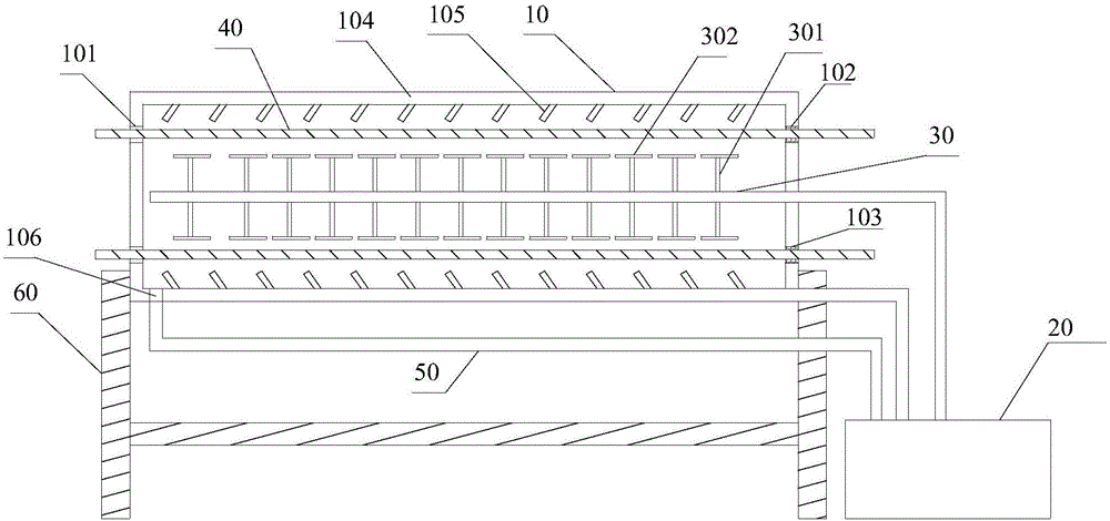
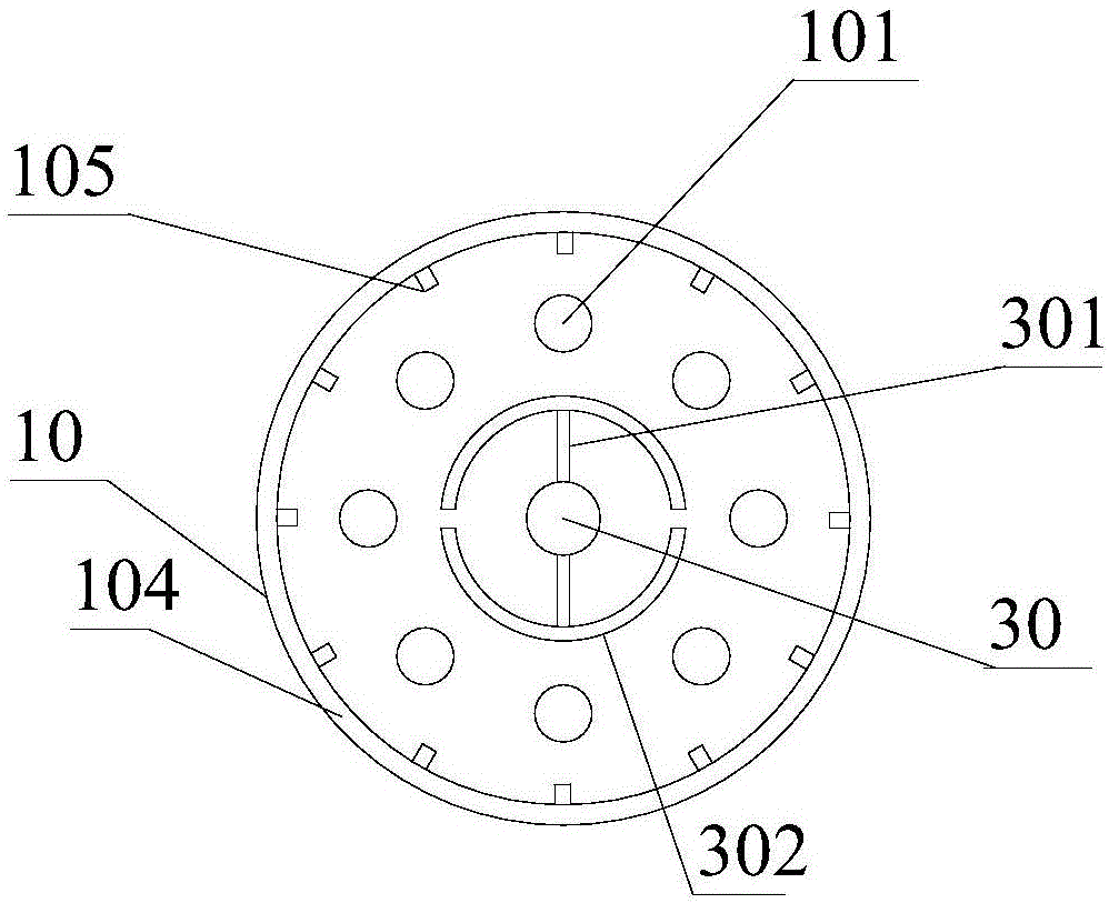
[0017] refer to figure 1 , figure 2 , the present invention proposes a water-cooled high-efficiency cooling device for wire rods, including a frame 60, a box body 10, a water tank 20, and a cooling water circulation pipe 50, wherein:

[0018] The box body 10 is installed on the frame 60, and a main water pipe 30 is provided on the inner axis of the box body 10. The length of the main water pipe 30 is adapted to the length of the box body 10. One end of the main water pipe 30 is sealed, and the other end is connected to the The water tank 20 outside 10 is connected, and the main water pipe 30 is located in the box body 10 and is provided with two rows of branch pipes 301 symmetrically. One end of the box body 10 is provided with a wire inlet 101, and the other end is provided with a wire outlet 102 in one-to-one correspondence with the wire inlet 101. The numbers of the wire inlet 101 and the wire outlet 102 are 8 respectively, and the wire inlet 101, The wire outlet holes 1...


PUM


Abstract

The invention provides a water cooling type efficient wire cooling device which comprises a tank body and a water tank. A main water pipe is arranged in the tank body. One end of the main water pipe is sealed, and the other end of the main water pipe is connected with the water tank arranged outside the tank body. Branch pipes are distributed on the section, located in the tank body, of the main water pipe and provided with semi-toroidal spray heads for spraying water to wires. One end of the tank body is provided with a plurality of wire inlet holes, and the other end of the tank body is provided with wire outlet holes in one-to-one correspondence with the wire inlet holes. The lower end of the tank body is provided with a water outlet. When the water cooling type efficient wire cooling device is in use, water is introduced into the main water pipe, the semi-toroidal spray heads spray water to the wires for cooling the wires, and then the water is drained out of the tank body through the water outlet. Due to the fact that the main water pipe is made communicated with the water tank, water in the main water pipe can be replaced in time, the cooling water in the main water pipe is good in flowability, the temperature of the cooling water always meets the requirement for wire cooling, the wires can be cooled in time, the multiple wires can be cooled at the same time, a cooling effect is good, working efficiency is high, and wire quality is high.

Description

technical field [0001] The invention relates to the technical field of wire rod processing, in particular to a water-cooled high-efficiency wire rod cooling device. Background technique [0002] In the wire rod production process, in order to meet the required physical properties of the product, it is necessary to carry out a water-through cooling control process on the finished product after rolling, and change the structure of the finished product to meet the required structure and physical properties of the product. The existing wire rod cooling device mainly uses a simple cooling water tank to cool the finished product after rolling. Since the surface temperature of the finished product just after rolling is extremely high, the fluidity of the cooling water in the cooling water tank is poor, so that the water temperature near the rolled product is higher than The water temperature of other parts, the water temperature of the upper part of the rolled product is higher tha...

Claims


Application Information

Patent Timeline
Patent Type & Authority Applications(China)
IPC IPC(8): B21B45/02
CPCB21B45/0233
Inventor 范建强舒晓雪陆斌
Owner 安徽奇祥汽车零部件有限公司
Learn More